


Magnum VS –48 Vdc User’s Manual Page 48
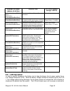
c) Interrupting Current Rating
Battery Visual and Safety Inspection
1. Check that the battery temperature probe is firmly attached to the battery.
2. Check the mechanical integrity of the battery framing, racking, or cabinet. Tighten
where necessary.
3. If there is a battery disconnect device fitted, ensure that it is properly connected and
protected.
4. Check the general appearance and cleanliness of the battery. Clean if necessary.
Use only approved cleaning materials.
5. Visually inspect each cell for the following, and clean and neutralize if necessary.
Document discrepancies on Site form accordingly.
a. Cracks.
b. Case leaks.
c. Post-seal leaks.
d. Pressure relief valve leaks (VRLA only).
e. Case swelling (VRLA only).
f. Terminal corrosion and connector corrosion.
6. Check the torque of all battery inter-cell connector in accordance with specifications.
Re-torque if necessary (annual only).
7. Measure and record ambient temperature.
7.3. Test
System Voltage Test
1. Verify with a voltmeter directly attached to the dc bus that the system voltage is correct.
2. System voltage should also agree with the battery float voltage set up in the battery
parameters section. Be sure to take into account the effects of temperature
compensation and battery recharge current limit.
Rectifier Current Share Test
Verify that the highest rectifier current and the lowest current are within 5 A of each other.
System Current Test
Verify the System current equal to the total of the rectifier currents. System current should
equal the total current of the loads as well as any battery current.
Rectifier Alarm Test
1. Verify that all of the rectifiers report RFA Alarm is off.
2. Remove 1 rectifier and verify that you get a Minor alarm for Rect 1 of n failure on the
controller and the customer remote alarm panel.