


Page 1-9
Quick View
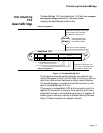
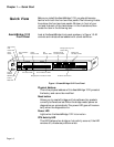
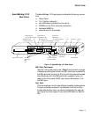
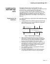
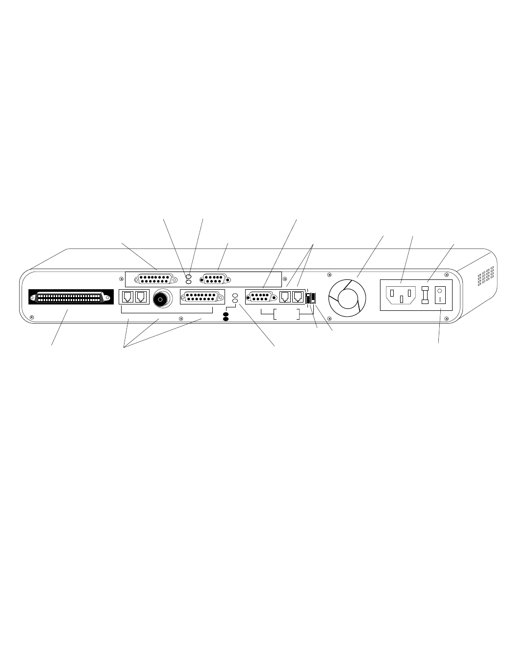
The AsantéBridge 1012 rear panel provides the following connec-
tors:
❏ 50-pin Telco
❏ 3-in-1 Uplink (network)
❏ two LED status indicators for the uplink
❏ RS 232 port for PC or terminal connection
❏ dedicated AMS link
❏ external port for the bridge
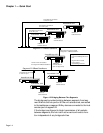
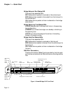
Figure 1-5 AsantéBridge 1012 Rear Panel
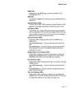
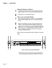
RJ21 Port Connector
Used for linking the twelve hub 10BaseT ports directly through
a telephone punchdown block; the RJ21 ports are in parallel to
the RJ45 ports on the front of the unit, but they cannot be used
simultaneously with the RJ45 ports. For example, if port 5 is
used on the front panel (RJ45), you cannot also use port 5 on
the RJ21 port.
3in1 Port
This is a single port with three different possible media options.
The port provides a network link between the hub (not the
bridge) and another hub or a network backbone. You can use
any one of the three types of connectors: AUI, BNC, or RJ45 In/
Out.
AsantéBridge 1012
Rear Panel
RJ21 10 BASE-T PORTS
IN or OUT
AUI
PARTITION
TRAFFIC
RS232
THROUGH
AMS LINK
UP=PC
DOWN=TERMINAL
END
3-IN-1 UPLINK
BNC
Spare Fuse in Fuse Holder
2A/250V Slow Blow Fuse
Replace Only With Fuse of Same Rating
Bridge External
Port AUI Connector
Bridge VT100
Local Management Port
Bridge/Hub
RS 232 Port
AMS Out-of-Band
Link Ports
Fan AC Power AC Line
Fuse
RJ21 Port Connector 3in1 Port:
RJ45 In/Out
BNC
AUI
3in1 Port Partition
and Traffic LEDs
On/Off Switch
Through/End
DIP Switch
Bridge External
Port Link/Receive LED
Bridge External
Port Collision LED
PC/Terminal
DIP Switch