


Page 1-12
Chapter 1 — Quick Start
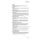
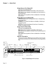
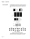
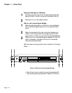
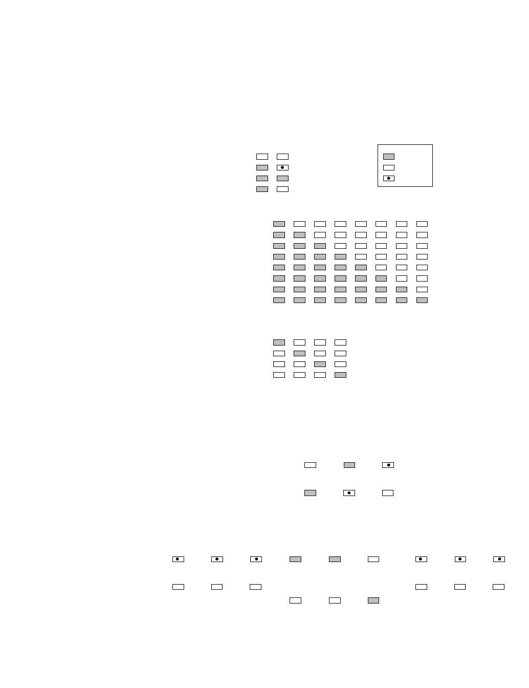
The AsantéBridge front panel LEDs provide status information on
both overall device utilization and for specific configuration and
fault conditions. Figure 1-6 shows you how to interpret the dis-
play.
Figure 1-6 Interpreting LED Status Indicators
See “AsantéBridge 1012 Front Panel” on page 1-6 for expanded
definitions for all LEDs on the AsantéBridge 1012 front panel.
Interpreting LEDs
Power/CPU Status
PWR CPU
LED Key
ON
OFF
FLASHING
Power Off, CPU Off
Power On, CPU Normal
Power On, CPU Failure
1
Utilization LED Interpretation
3 5 10 20 30 50
0-1%
+1-3%
+3-5%
+5-10%
+10-20%
+20-30%
+30-50%
+50-65% and over
Warning LED Interpretation
1, 2
Late Collision
Misaligned/CRC error
Runt/Fragmented packets
Short event/Missing SFG
1
Warnings may apply to any port on the hub.
Use the AsantéView Port Control command to isolate.
2
More than one warning type may be present.
Power On, CPU Failure
65+
Partition
1
Link present = Physical link at port or Link Test disabled
Link/Receive
No
partition
Link present
1
No traffic
Link present
Traffic
No link
Port
operator
partitioned
Port
auto
partitioned
Link/Partition LEDs
RCV
Receiving
packets
Forwarding
packets
Collisions
occurring
FWD COL
Bridge LEDs
No
traffic
No
traffic
No
collisions
STATUS
Transmitting
configuration
data
This bridge is on
standby in a
spanning tree
STANDBY
ACTIVE
Not transmitting
configuration
data
This bridge is
active in a
spanning tree
EXT PORT
RCV
Receiving
packets
Forwarding
packets
Collisions
occurring
FWD COL
No
traffic
No
traffic
No
traffic
HUB PORT