


Page 1-20
Chapter 1 — Quick Start
Connecting Devices to the AsantéBridge 1012
Now that you have pretested your AsantéBridge and have con-
nected it into your network as a bridge, the last step is to connect
Ethernet devices to the hub portion of the unit.
The AsantéBridge provides two options for device connections:
❏ Twelve RJ-45 ports on the front panel, which connect
on a one-to-one basis to single devices, or
❏ The 50-pin RJ21 connector on the rear panel, which
connects to a Telco punchdown block typically located
in the wiring closet in your building.
If you want to install the hub in a wiring closet using the RJ21
connector to make host connections, see Appendix C, “Pinouts
and Cable Specifications”.
What You Need
You need only the appropriate length straight-through RJ-45
extension cables. (If you want to build your own cables, see
Appendix C, “Pinouts and Cable Specifications” for details.)
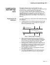
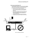
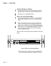
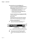
Using the front panel RJ45 ports
1
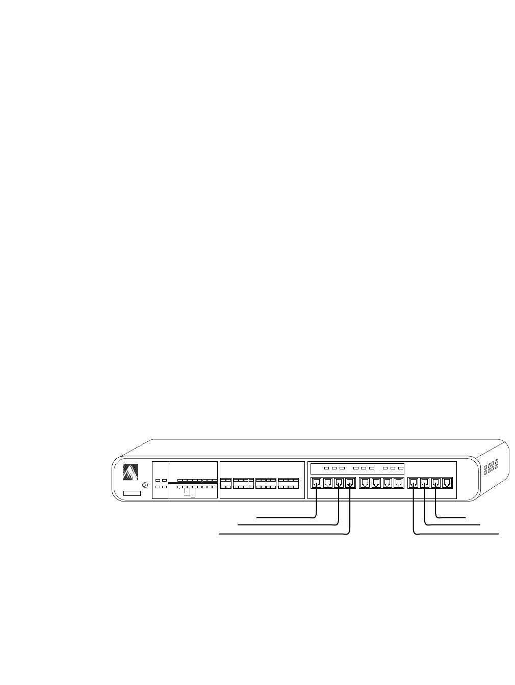
Connect the RJ-45 extension cables between the front
panel ports of the hub and the network devices.
Figure 1-11 Single-Hub Host Connections Using RJ-45 Extension Cables
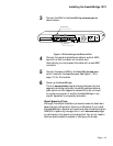
2
Connect the other ends of the RJ45 extension cables to
individual Ethernet devices such as Macintoshes, PCs,
printers, or other devices equipped with an Ethernet inter-
face.
ASANTE
RESET
PWR CPU
SNMPMSG
UTILIZATION
%
PARTITION
LINK/RECEIVE
BRDG
1
1
10BASE-T PORTS
AsantéHub 1012
1 3 5 10 20 30 50 65+ UPLINK
2 3 4 5 6 7 8 9 10 11 12
234 5678 910 11 12
COLLISION
%
13510+
Late Collision
Misaligned CRC
Runts/Fragments
Short Event/Missing SFD
STATUSSTANDBYACTIVERCV FWD COL
BRIDGE
RCV FWD COL
BRIDGE
0000944007B3
EXT PORT HUB
To Network Devices