


Page 9
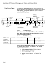
The Front Panel
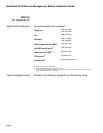
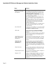
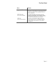
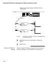
Table 2 identifies the NMM front panel components and explains
the function of each. It also lists LED interpretations where appro-
priate.
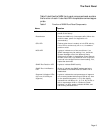
Table 2 Function of NMM Front Panel Components
Name Function
Ethernet MAC Address The physical address of this module and hub;
preset at the factory.
Reset button Resets the NMM only (interrupts traffic). When the
module resets, power on diagnostics run
automatically.
CPU LED Flashes when there is module or hub CPU activity;
if this LED is continuously off or on, a hardware
problem exists.
MSG LED Lights to indicate one of two conditions: 1) an
SNMP message may be waiting; if so, check the
System Message area of the Network Alerts
(Macintosh) window in AsantéView (Event Reports
window on the PC). 2) a checksum error may have
occurred in the image file when downloading; if so,
repeat the download.
SNMP Port Partition LED Lights to indicate SNMP activity.
SNMP Port Link/Receive
LED
Blinks to indicate that SNMP packets are being
transmitted to the NMM when an SNMP link is
established.
Segment Utilization LEDs
(top row of 8 LEDs per
segment)
Lights to indicate the total percentage of segment
(not module) bandwidth being utilized at any time
on the specified segment (1 or 2). Bar display
indicates hub utilization at 1, 3, 5, 10, 20, 30, 50, or
65+%, reported per 0.25 or 0.5 second. Green
indicates 1 to 20%; amber indicates 30-50%; and
red blinking indicates 65+%.