


Page 8
AsantéHub 2072 Network Management Module Installation Guide
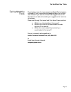
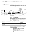
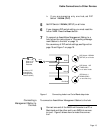
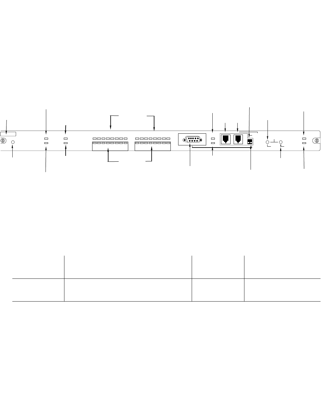
The Front Panel
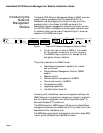
The NMM front panel has several LEDs, ports, connectors, and
switches, all used to monitor and maintain network activity and to
enable network management capabilities. Figure 3 shows the
parts of the NMM front panel.
Figure 3 The NMM Front Panel
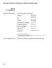
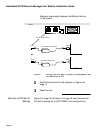
Some earlier models of the 2072 NMM have different DIP Switch
labels. Table 1 gives a summary of the names used on the front
panel and in the documentation.
Table 1 NMM DIP Switch Labels
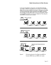
LEDs on the front panel display the status of the hub, NMM CPU,
and segment traffic (Segment 1 or Segment 2). The LEDs are
divided into five categories:
❏
NMM and segment status (CPU to utilization)
❏
Segment collision percentage
❏
Out-of-band and Setup status
❏
Segment Control (Segment 1 or Segment 2 or
none)
Change
Segment
Button
Reset
Button
t
hernet Address
CPU LED
MSG LED
SNMP Port
Partition
LED
RS232
Connector
Out-of-Band LED
SETUP
LED
AMS Link
Ports
DIP Switch 2
RS232/AMS LINK
CONFIGURATION
SEG 1
LED
SEG 2
LED
LC=Late/Collision
MC=Misaligned CRC
RF=Runts/Fragments
SM=Short Event/Missing SFD
SNMP
DIP Switch 1
ASANTEVIEW
OUT-OF-BAND
TERMINATION
CPU
MSG
PARTITION
LINK/RECEIVE
SNMP PORT
LC = Late Collision
MC = Misaligned CRC
RF = Runts/Fragments
SM = Short Event/Missing SFD
UTILIZATION %
OUT OF
BAND
SETUP
ASANTEVIEW
OUT-OF-BAND
TERMINATION
RS232/AMS LINK
CONFIGURATION
PRESS BOTH BUTTONS TO PROGRAM
1 3 5 10 20 30 50 65+
LC MC RF SM 1 3 5 10+
COLLISION %
UTILIZATION %
AMS LINK
SELECT
SLOT
CHANGE
SEGMENT
SEGMENT CONTROL
RESET
SEG 2
SEG 1
SEGMENT 2SEGMENT 1
COLLISION %
1 3 5 10 20 30 50 65+
LC MC RF SM 1 3 5 10+
AH2072NMM
RS-232
Link/Receive
LED
Collision%
LEDs
Utilization%
LEDs
Select Slot
Button
DIP Switch 1
(on the left)
ASANTEVIEW OUT-OF-BAND TERMINATION AMS LINK UP = THROUGH
DOWN = END
DIP Switch 2
(on the right)
RS232/AMS LINK CONFIGURATION RS232 UP = AMS PORT
DOWN = SETUP