


Page 7
Installation
2
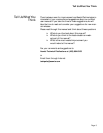
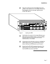
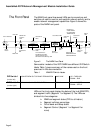
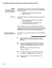
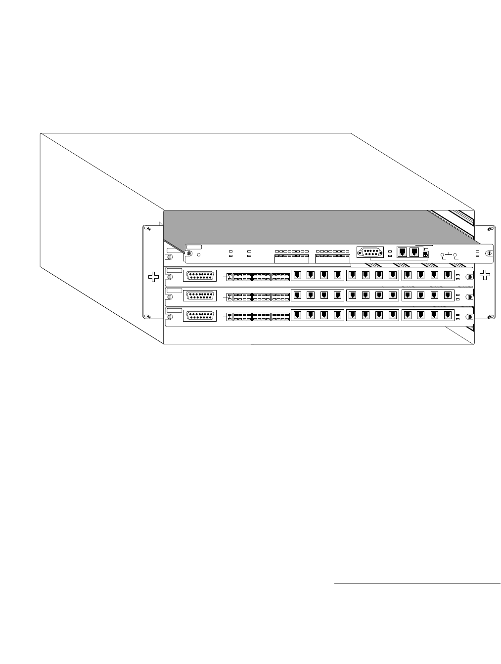
Align the module with the inside edges of the card
guides on any available slot in the chassis. Gently slide
the module in until you can begin tightening the
screws. See Figure 2.
Figure 2 Installing the NMM
3
Hand-tighten the module to the chassis. Make sure you
fasten both spring-loaded screws in unison and apply
the same amount of torque so that the module
attaches evenly to the chassis.
4
If the power to the hub was on when you installed the
NMM, reset the hub. If you powered down the hub
before installing the NMM, power up at this point.
5
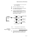
Check that the CPU LED (located to the right of the
Reset button) blinks. A blinking CPU LED indicates
that the NMM is functioning properly.
P
ARTITION
10
BASE
T
P
ORTS
SEG1
SEG 0
1234 5678 9101112
UPLINK 0
AUI
AH2072H12-RJ45
910111256781234
L
INK/
R
ECEIVE
P
ARTITION
10
BASE
T
P
ORTS
SEG1
SEG 0
1234 5678 9101112
UPLINK 0
AUI
AH2072H12-RJ45
910111256781234
L
INK/
R
ECEIVE
P
ARTITION
10
BASE
T
P
ORTS
SEG1
SEG 0
1234 5678 9101112
UPLINK 0
AUI
AH2072H12-RJ45
910111256781234
L
INK/
R
ECEIVE
P
ARTITION
10
BASE
T
P
ORTS
SEG1
SEG 0
1234 5678 9101112
UPLINK 0
AUI
AH2072H12-RJ45
910111256781234
L
INK/
R
ECEIVE
CPU
MSG
PARTITION
LINK/RECEIVE
SNMP PORT
LC = Late Collision
MC = Misaligned CRC
RF = Runts/Fragments
SM = Short Event/Missing SFD
OUT OF
BAND
SETUP
ASANTEVIEW
OUT-OF-BAND
TERMINATION
RS232/AMS LINK
CONFIGURATION
PRESS BOTH BUTTONS TO PROGRAM
1 3 5 10 20 30 5065+
LCMC RFSM 1 3 5 10+
COLLISION %
AMS LINK
SELECT
SLOT
CHANGE
SEGMENT
SEGMENT CONTROL
RESET
SEG 2
SEG 1
COLLISION %
1 3 5 10 20 30 5065+
LCMC RFSM 1 3 5 10+
AH2072NMM
RS-232
SEGMENT 1 SEGMENT 2
UTILIZATION % UTILIZATION %