


Introduction
Page 1-8
Tools and
Materials
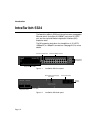
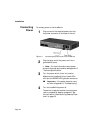
Some tools and materials that are not supplied with the
IntraSwitch 5324 are needed to connect the switch to an
Ethernet network.
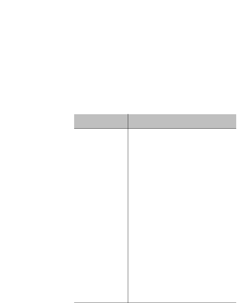
The table below lists the tools and materials required for
connecting devices to the switch’s ports, for installing an MII
module, and for rack-mounting the switch.
▲ Important: For specific instructions on con-
necting network devices to the IntraSwitch, see
“Connecting to the Network” on page 2-7.
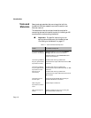
Table 1-1 Tools and Materials Required
Action Tool/Material Required
Connecting 10Base-
T ports or 10/100 port
Standard Category 3, 4 or 5 UTP straight-
through cable with RJ-45 connectors.
Standard Category 5 UTP cross-over cable
with RJ-45 connectors.
Connecting 100Base-
FX port (optional MII
expansion module)
Dual 62.5/125 micron graded-index
multimode fiber optic cable fitted with an SC
connector.
Connecting 10Base-
FL port (optional MII
expansion module
with SC or ST
connectors)
Dual 62.5/125 micron graded-index
multimode fiber optic cable fitted with an SC
connector.
Dual 62.5/125 micron graded-index
multimode fiber optic cable fitted with a dual
ST connector.
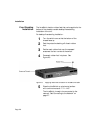
Connecting to the
Console port
Straight-through RS-232 cable with 9-pin
male D-subminiature connector.
Removing MII
expansion module’s
cover
Small Phillips screwdriver.
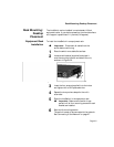
Rack-mounting the
switch
Phillips screwdriver (#2) for mounting the
two rack brackets on the unit.