


ASUS Terminator 1 C3 barebone systemASUS Terminator 1 C3 barebone system
ASUS Terminator 1 C3 barebone systemASUS Terminator 1 C3 barebone system
ASUS Terminator 1 C3 barebone system
2-152-15
2-152-15
2-15
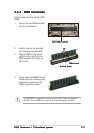
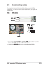
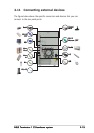
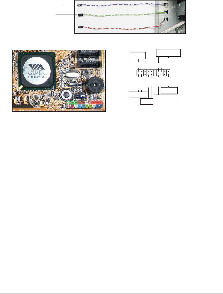
2.9 Re-connecting cables
You may have disconnected some cables when you were installing
components. You must re-connect these cables before you replace the
chassis cover.
2.9.12.9.1
2.9.12.9.1
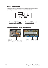
2.9.1
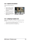
LED cablesLED cables
LED cablesLED cables
LED cables
•
Connect the
power switchpower switch
power switchpower switch
power switch and
power LEDpower LED
power LEDpower LED
power LED cables to their respective
leads in the PANEL connector on the motherboard.
•
Connect the
HDD LEDHDD LED
HDD LEDHDD LED
HDD LED cable to the 2-pin lead marked IDELED.
Power switchPower switch
Power switchPower switch
Power switch
Power LEDPower LED
Power LEDPower LED
Power LED
HDD LEDHDD LED
HDD LEDHDD LED
HDD LED
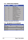
PANELPANEL
PANELPANEL
PANEL
* Requires an ATX power supply.
PLED
Ground
PWRBIN
+5 V
+5V
Speaker
SPEAKER
PLED
Ground
RESET
SMI
ExtSMI#
Ground
Reset
Ground
Ground
PWRBTN
IDE_LED-
IDE_LED+
IDELED