


ASUS Terminator T1 C3 barebone systemASUS Terminator T1 C3 barebone system
ASUS Terminator T1 C3 barebone systemASUS Terminator T1 C3 barebone system
ASUS Terminator T1 C3 barebone system
4-114-11
4-114-11
4-11
13.13.
13.13.
13.
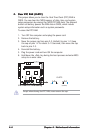
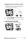
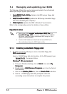
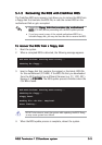
System panel connector (20-pin PANEL)System panel connector (20-pin PANEL)
System panel connector (20-pin PANEL)System panel connector (20-pin PANEL)
System panel connector (20-pin PANEL)
This connector supports several chassis-mounted functions.
C3V
®
C3V System panel connectors
* Requires an ATX power supply.
PLED
Ground
PWRBIN
+5 V
+5V
Speaker
SPEAKER
PLED
Ground
RESET
SMI
ExtSMI#
Ground
Reset
Ground
Ground
PWRBTN
IDE_LED-
IDE_LED+
IDELED
NEVER connect a
USB cable USB cable
USB cable USB cable
USB cable to the IEEE 1394a connector. Doing so
will damage the motherboard!
12.12.
12.12.
12.
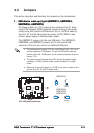
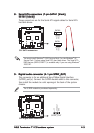
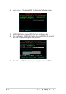
IEEE 1394a connectors (10-1 pin IE1394_1, IE1394_2)IEEE 1394a connectors (10-1 pin IE1394_1, IE1394_2)
IEEE 1394a connectors (10-1 pin IE1394_1, IE1394_2)IEEE 1394a connectors (10-1 pin IE1394_1, IE1394_2)
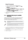
IEEE 1394a connectors (10-1 pin IE1394_1, IE1394_2)
[optional]
These connectors are for IEEE 1394a ports. Connect the IEEE 1394a
module cable to this connector, then install the module to a slot
opening at the back of the system chassis.
C3V
®
C3V IEEE 1394 connectors
1
TPA0-
GND
TPB0-
+12V
GND
TPA0+
GND
TPB0+
+12V
IE1394_1
1
TPA0-
GND
TPB0-
+12V
GND
TPA0+
GND
TPB0+
+12V
IE1394_2