


2-18
Chapter 2: Hardware information
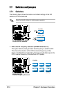
2.8 Connectors
This section describes and illustrates the internal connectors on the
motherboard.
Always connect ribbon cables with the red stripe to Pin 1 on the
connectors. Pin 1 is usually on the side closest to the power connector
on hard drives and CD-ROM drives, but may be on the opposite side
on floppy disk drives.
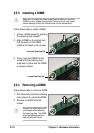
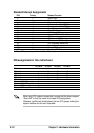
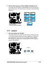
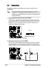
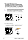
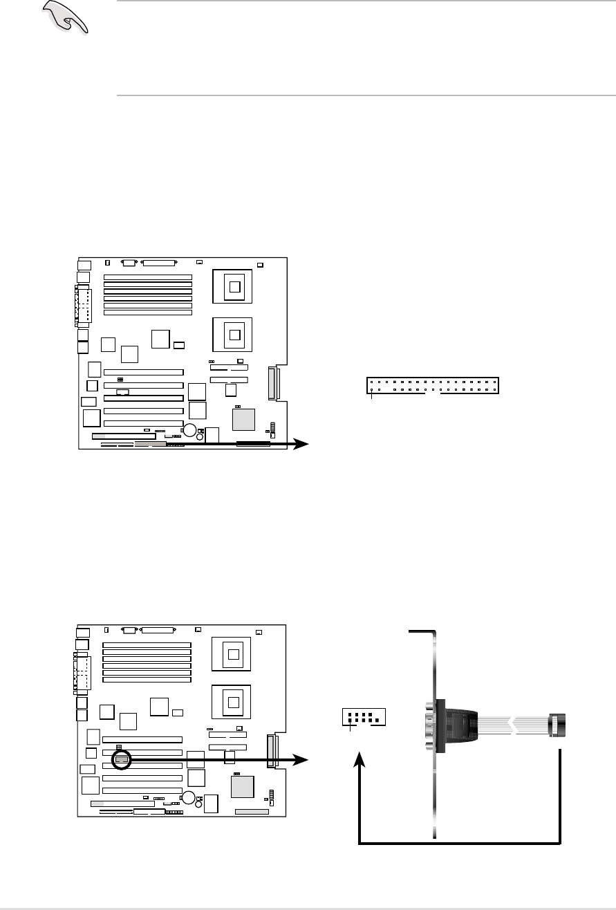
1. Floppy disk drive connector (34-1 pin FLOPPY)
This connector supports the provided floppy drive ribbon cable. After
connecting one end to the motherboard, connect the other end to the
floppy drive. (Pin 5 is removed to prevent incorrect insertion when
using ribbon cables with pin 5 plug).
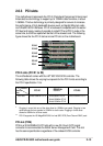
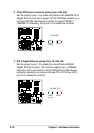
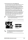
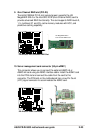
2. Serial port 2 connector (10-1 pin COM2)
This connector accommodates a second serial port using an optional
serial port bracket. Connect the bracket cable to this connector then
install the bracket into a slot opening at the back of the system chassis.
PR-DLS533
NOTE: Orient the red markings on
the floppy ribbon cable to PIN 1.
PR-DLS533 Floppy Disk Drive Connector
PIN 1
FLOPPY
PR-DLS533
PR-DLS533 Serial COM2 Connector
PIN 1