


ASUS PR-DLS533 motherboard user guide
2-27
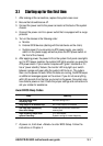
• System Power LED Lead (3-1 pin PLED)
This 3-1 pin connector connects to the system power LED. The LED
lights up when you turn on the system power, and blinks when the
system is in sleep mode.
• System Message LED Lead (2-pin MLED)
This 2-pin connector is for the system message LED that indicates
receipt of messages from a fax/modem. The normal status for this LED
is OFF, when there is no incoming data signal. The LED blinks when
data is received. The system message LED feature requires an ACPI
OS and driver support.
• System Warning Speaker Lead (4-pin SPEAKER)
This 4-pin connector is for a chassis-mounted speaker.
• ATX Power Switch / Soft-Off Switch Lead (2-pin PWR)
This connector connects a switch that controls the system power.
Pressing the power switch turns the system between ON and SLEEP,
or ON and SOFT OFF, depending on the BIOS or OS settings.
Pressing the power switch while in the ON mode for more than 4
seconds turns the system OFF.
• Reset Switch Lead (2-pin RESET)
This 2-pin connector connects to the case-mounted reset switch for
rebooting the system without turning off the system power.
• Keylock Lead (2-pin KEYLOCK)
This lead connects to a chassis-mounted switch to allow use of the
keyboard lock feature.
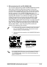
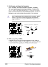
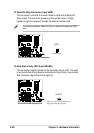
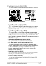
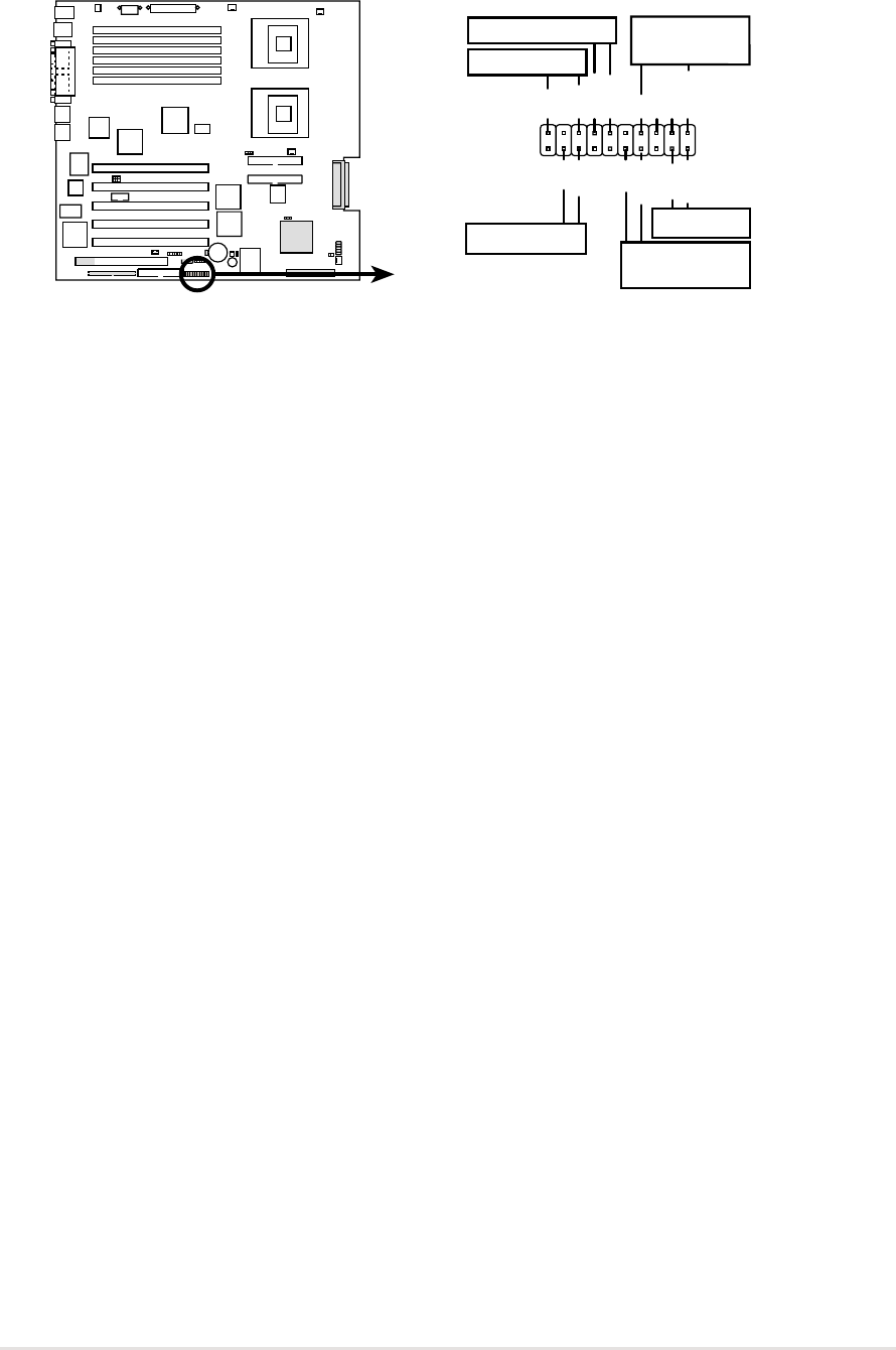
16. System panel connector (20-pin PANEL)
This connector accommodates several system front panel functions.
PR-DLS533
PR-DLS533 System Panel Connectors
PLED
MLED
PWR
+5 V
Keylock
+5V
Speaker
Speaker
Connector
Power LED
Ground
+5 V
Reset SW
Message LED
Ground
Reset
IDELED+
IDELED-
Ground
Keyboard Lock
ATX Power
Switch*
1
11
10
20