Chapter 2: Installation and Configuration 9
Chapter 2: Installation and Configuration
Hardware Overview
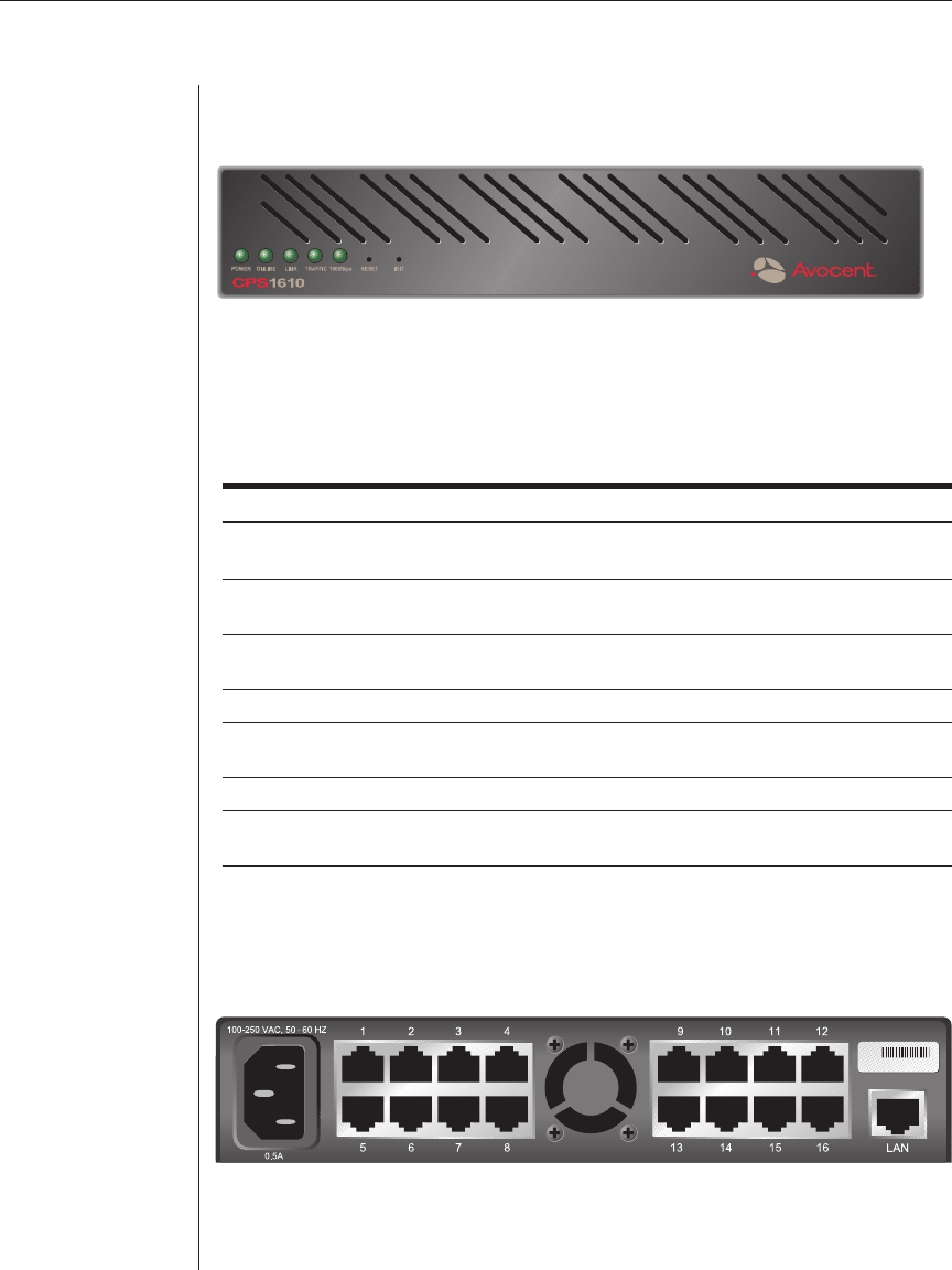
Figure 2.1 shows the front panel of a CPS1610.
Figure 2.1: CPS1610 Front Panel
The lower left area of the front panel contains five LEDs and two buttons,
which are described in the following table.
CPS LEDs and Buttons
LED/Button Description
POWER The POWER LED illuminates when the CPS is connected to a
power source.
ONLINE The ONLINE LED illuminates steadily (not blinking) when the CPS
self-test and initialization procedures complete successfully.
LINK The LINK LED illuminates when the CPS establishes a connection
to the network.
TRAFFIC The TRAFFIC LED blinks when there is network traffi c.
100MBps The 100MBps LED illuminates when the CPS is connected to a 100
MBps LAN.
RESET The RESET button, when pressed, reboots the CPS.
INIT The INIT button, when pressed, restores the CPS to factory defaults;
for more information, see Reinitializing the CPS in this chapter.
As shown in Figure 2.2, the back of the CPS contains 8 (CPS810) or 16
(CPS1610) RJ-45 connectors for serial cabling, a LAN connector for a 10BaseT
or 100BaseT interface cable and a power receptacle.
Figure 2.2: CPS1610 Back Panel


