


92 en | Operation VideoJet X10
DOC | V4.0 | 2009.06 Installation and Operating Manual Bosch Security Systems
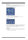
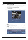
View Control
Control options for peripherals (for example a pan/tilt head or dome camera) depend on the
type of unit installed and on the configuration of the VideoJet X10.
If a controllable unit is configured and connected to the VideoJet X10, the controls for the
peripheral are displayed next to the video image.
1. To control a peripheral, click the appropriate controls.
2. Move the mouse cursor over the video image. Additional options for controlling
peripherals are displayed with the mouse cursor.
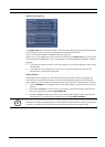
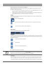
Digital I/O
The alarm icons Input 1 to Input 4 are for information purposes and indicate the status of an
alarm input: When an alarm is triggered, the corresponding icon lights up blue. The unit's
configuration determines whether the alarm is displayed, as well as additional details (see
Section 5.15 Advanced Mode: LIVEPAGE Functions, page 43).
Triggering Relay
You can switch connected units using the relays in the VideoJet X10 (for example lights or
door openers).
X To activate this, click the icon for the corresponding relay next to the video image. The
icon will be red when the relay is activated.