


Chapter 3: Local Management
3-10 HSIM-A6DP User’s Guide
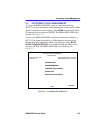
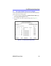
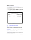
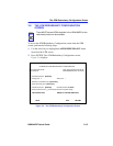
3.6.1 ATM Connection Setup Screen Fields
The ATM Connection Setup screen allows the user to view the current
configured virtual connections, (PVCs and SVCs) on the HSIM-A6DP.
This screen also allows the user to access the Add/Delete Entry screen,
which is used to create, modify, or delete PVCs.
The following list explains each of the ATM Connection Setup screen
fields:
ATM Port Current Connections (Read-Only)
This field displays the number of current connections on the
HSIM-A6DP.
IF (Read-Only)
This field represents the virtual MIB-II interface that this Virtual Channel
(VC) was created on. This field can represent both Switched Virtual
Channels (SVCs), and Permanent Virtual Channels (PVCs).
PORT (Read-Only)
This field displays the port (APIM) on which the PVC or SVC resides.
VPI (Read-Only)
This field displays the Virtual Path Identifier of the connection. This field
reads 0 or 1.
VCI (Read-Only)
This field displays the Virtual Channel Identifier of the connection. This
field should read between 1 and 1020.
NOTE
The first two connections shown in Figure 3-4 (with VPI, VCI
values of 0, 5 and 0,16 respectively) represent ILMI and UNI.
These two connections, even if they are disabled in the
Signalling screen (Section 3.15), will always display on the
ATM Connection Setup screen.