


SmartSwitch Router User Reference Manual 333
Chapter 22: WAN Configuration Guide
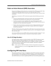
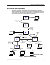
Multi-Router WAN Configuration
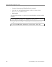
The following is a diagram of a multi-router WAN configuration encompassing three
subnets. From the diagram, you can see that R1 is part of both Subnets 1 and 2; R2 is part
of both Subnets 2 and 3; and R3 is part of subnets 1 and 3. You can click on the router label
(in blue) to jump to the actual text configuration file for that router:
Figure 24. Multi-router WAN configuration
R5
R3
R4
R2
R1
R6
SmartBits
IP packet
generator
Video
Client
Win 95
SmartBits
IP
generator
SmartBits
IP packets
Video
Server
Win NT
SmartBits
IP packets
50.50.50.5
50.50.50.15
et.1.1
100.100.100.5
100.100.100.4
100.100.100.4
100.100.100.3
se.4.1
se.6.3
se.6.1
se.2.1
hs.4.2
hs.4.1
hs.7.2hs.3.1
et.1.1 et.1.2
hs.7.1hs.3.2
et.1.1
hs.7.1
hs.3.1
et.15.2 et.15.1
30.30.30.3
30.30.30.13
100.100.100.3 130.130.130.3
100.100.100.1 130.130.130.2
200.200.200.20020.20.20.12
20.20.20.2 200.200.200.1
120.120.120.1 120.120.120.2
100.100.100.1
100.100.100.6
100.100.100.100
60.60.60.6
60.60.60.16
100.100.100.6
Frame Relay
wan-encaps.
subnet S1
VC = 106
PPP wan-encaps.
subnet S2
Frame Relay
wan-encaps.
subnet S1
VC = 103
PPP wan-encaps.
subnet S3
PPP wan-encaps.
subnet S1
Frame Relay
wan-encaps.
subnet S1
VC = 304
Legend:
Router Connections on Subnet 1
Router Connections on Subnet 2
Router Connections on Subnet 3