


SmartSwitch Router User Reference Manual 99
Chapter 7: VRRP Configuration Guide
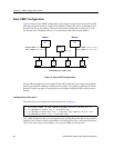
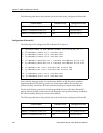
On line 5, Router R1 associates IP address 10.0.0.2/16 with virtual router VRID=2.
However, since Router R1 does not own IP address 10.0.0.2/16, it is not the default Master
for virtual router
VRID=2.
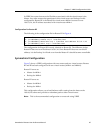
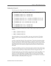
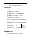
Configuration of Router R2
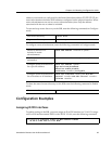
The following is the configuration file for Router R2 in Figure 5.
On line 1, Router R2 is made owner of IP address 10.0.0.2/16. Line 5 associates this IP
address with virtual router
VRID=2, so Router R2 is the Master for virtual router VRID=2.
Line 4 associates IP address 10.0.0.1/16 with virtual router
VRID=1, making Router R2 the
Backup for virtual router
VRID=1.
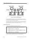
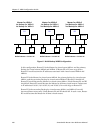
Multi-Backup Configuration
Figure 6 shows a VRRP configuration with three routers and three virtual routers. Each
router serves as a Master for one virtual router and as a Backup for each of the others.
When a Master router goes down, one of the Backups takes over the IP addresses of its
virtual router.
In a VRRP configuration where more than one router is backing up a Master, you can
specify which Backup router takes over when the Master goes down by setting the
priority for the Backup routers.
1: interface create ip test address-netmask 10.0.0.2/16 port et.1.1
!
2: ip-redundancy create vrrp 1 interface test
3: ip-redundancy create vrrp 2 interface test
!
4: ip-redundancy associate vrrp 1 interface test address 10.0.0.1/16
5: ip-redundancy associate vrrp 2 interface test address 10.0.0.2/16
!
6: ip-redundancy start vrrp 1 interface test
7: ip-redundancy start vrrp 2 interface test