


97
Switch Configuration SmartStack STS16-20D/STS16-20R Token Ring Switches Installation and User Guide
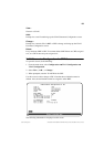
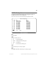
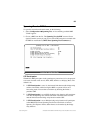
SNMP Configuration Menu
The next menu item in the
Configuration
menu is
SNMP Configuration..
.
This item opens a menu that is explained in Chapter 8, “Monitoring the Network
with SNMP”.
The next section describes the spanning tree protocol and the STP menus that you
access from the
Configuration
menu.
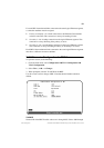
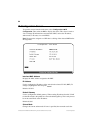
Spanning Tree Protocol
The spanning tree protocol (STP) is a bridge-to-bridge link management protocol
that provides path redundancy while preventing undesirable loops. To provide path
redundancy, the spanning tree protocol defines a tree that spans all switches and
bridges in the extended network. If one of the network segments in the tree becomes
inaccessible, STP reconfigures this tree to reestablish the links. To prevent loops,
STP selects just one SmartStack STS16-20D/STS16-20R port as the designated
path to the root, assigning it the Forwarding, or active state. It assigns all other ports
the blocking, or standby, state. A port in the blocking state does not forward any
transmitted frames in any direction.
The IBM Spanning Tree Protocols will only block for spanning tree explorer
frames and will work on the BRF level in the switch.
The IEEE spanning tree can operate on two levels—BRF and CRF. It is possible to
have a spanning tree entity running on the bridge entity and a spanning tree entity
running in every CRF at the same time. Logically, there is an internal port between
the BRF and the CRFs. All BRFs in the switch uses the same bridge id, which
prevents running the spanning tree protocol between two BRFs on the same switch.
All CRFs use a unique bridge id. This means that the ports in a CRF can be
connected.
➽ Note
: On SmartStack STS16-20D, only ports 17 to 20 support the spanning tree
protocol. Ports 1 to 16 are always in a forwarding state. (On SmartStack STS16-
20R all ports support the spanning tree protocol.)
➽ Note:
In the VLAN STP configuration menu, for the selection of port priority/port
path cost, select only the ports which are part of the current VLAN. Do not
configure ports in other VLANs.
The path cost indicates the relative speed of the segment: The higher the speed of
the segment, the lower the path cost. Switches and bridges in the network attempt
to determine the path to the route with the lowest path cost. IEEE 802.1D
recommends that you assign path costs using the following formula:
Path cost = 1000 / LAN speed in Mbps