


141
Switch Configuration SmartStack STS16-20D/STS16-20R Token Ring Switches Installation and User Guide
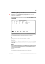
DSRR Configuration
Dynamic Source Route Recovery enables a set of switches performing source route
bridging between the same legacy Token-Ring and emulated Token-Ring (or the
same pair of legacy Token-Rings) to handle link or switch failures without session
loss. During normal operation, each switch forwards frames containing a Specific
Route Descriptor. If a switch or its link to the legacy or emulated Token-Ring fails,
another switch will after, typically, less than 3 seconds start forwarding frames
containing the Route Descriptor associated with the failing switch.
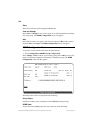
The configuration of DSRR redundancy for source routing between two Token-
Rings is performed in two steps:
•
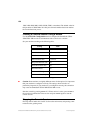
Configuration of a VLAN per switch, defining the normal source route bridging
function between the two rings in question. Note that the CRFs are not allowed to
have more than one port each, and that the ring number must be specified.
•
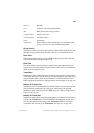
Configuration of timer values and port pairs used for back-up. The timer values
configured on each participating switch must be identical.
For an overview on DSRR, see “Dynamic Source Route Recovery” on page 32 in
Chapter 2, “Switch Overview”.
➽ Note!
Making the LANE Clients that correspond to the backup Virtual ATM Ports
(VAPs) join the same Emulated LAN (ELAN) as those that correspond to the active
VAPs, may depend on properly configuring a possible LAN Emulation Client
Server (LECS) and/or the SSIM-A2-01/SSIM-A8-01 ATM 155 SmartStack
Interface Modules. The primary policy used for assigning LANE Clients to ELANs
is by ELAN name. The backup LANE Clients will attempt to join an ELAN with
the same name as the active LANE Clients. Consequently, the backup LANE
Clients will join the correct ELAN if the active LANE Clients were successfully
assigned to an ELAN based on the default “by-name” policy. In other situations (for
example, when the LECS is not employed), the following information may be of
use for LECS configuration:
•
A standby LANE Client will join with an ATM address, which only differs
from that of the corresponding active LANE Client in the selector byte.
•
A standby LANE Client will join with a source MAC address, which is
constructed as follows:
0x02
<
random byte
><
4 last bytes of switch MAC address
>.
Restrictions
When configuring a DSRR group, please note the following restrictions:
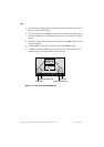
•
The primary port and the backup for the primary port (see Figure 27) must be
connected to same legacy Token-Ring.