


Projector Installation and Assembly
CHRISTIE DIGITAL SYSTEMS P35GPS Projector
March, 2004
3-5
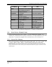
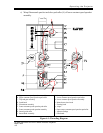
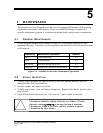
Terminal TB1 Connection
1 Motor (A-C neutral)
2 Motor switch lead (A-C hot, switched externally)
3 Framing lamp and cooling fan (A-C hot)
4 Changeover coil OPEN (A-C, switched externally)
5 Changeover coil CLOSE (A-C, switched externally)
6 Framing lamp, cooling fan, and changeover (A-C neutral).
Figure 3-4: Table of A-C Terminal Connections
The voltage and frequency rating of the projector (shown on the
nameplate) must match the power line frequency and voltage being
used.