


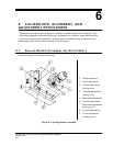


P35GPS Dual Lens Turret Projector
CHRISTIE DIGITAL SYSTEMS P35GPS Projector 6-4
March, 2004
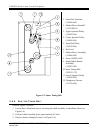
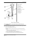
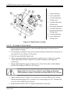
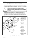
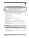
1: Clamp mounting
2: Focus adjustment
3: Vertical adjustment
locking screw
4: Azimuth adjustment
locking screw
5: Horizontal adjustment
6: Azimuth adjustment
7: Horizontal adjustment
locking screw
8: Vertical adjustment
9: Focus adjustment
locking screw
Figure 6-2: Digital Reader Assembly
6.2.2. ALIGNMENT P ROCEDURE
1. Remove analog reader assembly, or rotate assembly downward, for easier access to
Digital Reader Assembly.
2. Set adjustment assembly to center of travel path in both horizontal (item 5 in Figure 6-2)
and vertical (item 8 in Figure 6-2) directions.
3. Run film loop with Dolby Digital track.
4. Adjust vertical positioning by pivoting entire assembly (item 1 in Figure 6-2) and fine
vertical adjustments (item 8 in Figure 6-2) to achieve maximum video signal on
oscilloscope.
5. Adjust with threaded lens (item 2 in Figure 6-2) at front of assembly to obtain highest
possible focus reading on DRAS or QC software.
Digital reader has been factory-aligned to meet Dolby specifications.
Field adjustment requires oscilloscope and either DRAS or QC software.
6. Adjust azimuth (item 6 in Figure 6-2) to read zero ±2 mils with DRAS or QC software.
7. Adjust lateral positioning (item 5 in Figure 6-2) to center image on CCD. It should read
zero ±0.5 mils on DRAS or QC software.
8. Magnification should be 100 ±2%; adjust focal distance if necessary.