


P35GPS Dual Lens Turret Projector
CHRISTIE DIGITAL SYSTEMS P35GPS Projector 6-2
March, 2004
6.1.1. PRELIMINARY P ROCEDURES
Refer to Figure 3-2 on page 3-34 for a list of the tools, equipment, and materials required.
1. Verify that LED is operational and lens is clean.
2. Verify cell wiring for proper left/right wiring to cinema processor.
6.1.2. CELL P OSITIONING: VERTICAL ALIGNMENT
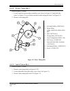
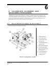
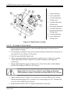
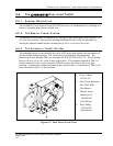
1. Loosen 10-32 allen set screw on side of assembly (item 3 in Figure 6-1).
2. Run Dolby Cat. 69 tone.
3. Adjust vertical position of cell (item 8 in Figure 6-1) for maximum output level.
4. Tighten locking screw on side of cell adjustment assembly. (item 3 in figure 6-1).
5. Adjust cinema processor's pre-amplifier gains for left and right tone reference levels.
6.1.3. HORIZONTAL( LATERAL) ALIGNMENT
1. Loosen 10-32 allen set screw on bottom of cell adjustment assembly (item 7 in Figure
6-1).
2. Run Buzz Track film.
3. Adjust lateral position of cell (item 5 in Figure 6-1) until there is no output at processor's
test points. If output is present on both left and right test points, increase focal distance
between lens and cell.
4. Tighten locking screw on bottom of cell adjustment assembly. (item 7 in Figure 6-1).
6.1.4. FOCUS AND A ZIMUTH
1. Loosen 10-32 allen set screw in hole on side of assembly (item 4 in Figure 6-1).
2. Turn cinema processor's pre-amplifier Hf adjustments counterclockwise to minimum
settings.
3. Run Dolby Cat. 69 Pink Noise film (not older than 1992).
4. Adjust Focus (item 2 in Figure 6-1) and Azimuth (item 6 in Figure 6-1) for maximum
high frequency response and phase coherence.
5. Carefully lock focus adjustment (9) and azimuth locking screw (4).
6. Turn cinema processor's pre-amplifier Hf adjustments clockwise until real-time analyzer
shows flat frequency response to 16 kHz.
7. Verify that both channels have identical frequency response.