


Calibration, Alignment, and Adjustment Procedures
CHRISTIE DIGITAL SYSTEMS P35GPS Projector
March, 2004
6-5
9. Adjust LED power supply output for 4 ±0.5V of video amplitude if necessary.
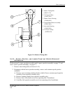
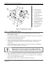
10. Lock all adjustment (items 3, 4, 7, and 9 in Figure 6-2).
6.3. DASHPOT ADJUSTMENT
1. Turn hex-slotted screw counter clockwise at bottom of dashpot assembly through access
hole in projector bottom plate, until friction of dashpot is at lowest point.
2. Run wow and flutter test film and increase friction by turning hex slotted screw, at
bottom of dashpot assembly, clockwise until best result is obtained.
6.4. INNER, OUTER, AND SHUTTER TIMING BELT ADJUSTMENT
WARNING
NEVER adjust belts with power applied!
Belt tension should be kept as loose as possible while remaining tight enough to drive all
mechanisms. To adjust belt tension, follow procedures in Sections 6.4.1 through 6.4.3.
Do not over-tighten belts. If belts are too tight, projector will not
operate properly, and projector parts will wear prematurely.
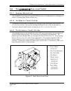
6.4.1. INNER T IMING B ELT
Refer to Figure 5-3 on page 5-4.
1. Loosen inner tensioner locking screw (item 1 in Figure 5-3).
2. Adjust inner timing belt pulley until belt deflection is 0.25 inch (item 10 in Figure 5-3).
Belt should be just tight enough to prevent slapping.
3. Tighten locking screw (item 1 in Figure 5-3).
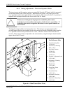
6.4.2. SHUTTER T IMING BELT
Refer to Figure 5-4 on page 5-5.
1. Loosen three screws securing adjust plate (item 5 in Figure 5-4).
2. Pull adjust plate (item 5 in Figure 5-4) up until belt deflection is 0.25 inch. It should be
just possible to touch belt together at its midpoint.
3. Tighten screws firmly.