


Table of contents
CHRISTIE DIGITAL SYSTEMS P35GPS Projector
March, 2004
v
LIST OF FIGURES AND TABLES
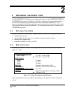
Figure 2-1: Table of Equipment Specifications .......................................................................... 2-1
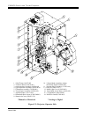
Figure 2-2: Projector, Front View............................................................................................... 2-2
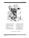
Figure 2-3: Projector, Rear View................................................................................................ 2-3
Figure 3-1: Installing the Projector .............................................................................................3-2
Figure 3-2: Tools and Materials Required for Assembly and Maintenance............................... 3-3
Figure 3-3: Projector Wiring Diagram (50- and 60-Hz models) ................................................3-4
Figure 3-4: Table of A-C Terminal Connections........................................................................3-5
Figure 4-1: Threading Diagram ..................................................................................................4-3
Figure 5-1: Schedule for Periodic Maintenance Operations.......................................................5-1
Figure 5-2: Outer Timing Belt ....................................................................................................5-3
Figure 5-3: Inner Timing Belt..................................................................................................... 5-4
Figure 5-4: Shutter Timing Belt..................................................................................................5-5
Figure 6-1: Analog Reader Alignment and Adjustments............................................................ 6-1
Figure 6-2: Digital Reader Assembly ......................................................................................... 6-4
Figure 6-3: Dual Turret (Front View) .........................................................................................6-7
Figure 6-4: Dual Turret (Rear View) .......................................................................................... 6-8
Table A-1: P35GPS Projector Replaceable Assemblies and Components................................ A-1
Figure B-1: Changeover Douser Assembly (P/N 196601-001) ................................................. B-2
Table B-1: Changeover Douser Assembly Parts List ................................................................ B-3
Figure B-2: Automatic Curved Trap and Gate Assembly (P/N 196556-001) ........................... B-4
Table B-2: Parts List for Automatic Curved Trap and Gate Assembly..................................... B-7
Figure B-3: Fixed Idler Assembly (P/N 194756-001) ............................................................... B-8
Table B-3: Fixed Idler Assembly Parts List............................................................................... B-8
Figure B-4: Fixed Idler Assembly, Flanged (P/N 194756-002) ................................................ B-9
Table B-4: Fixed Idler Roller Assembly, Flanged, Parts List.................................................... B-9
Figure B-5: Jackshaft Assembly (P/N 194810-001) ................................................................ B-10
Table B-5: Jackshaft Assembly Parts List ............................................................................... B-10
Figure B-6: Center and Upper Constant-Speed Sprocket Assembly (P/N 194856-001)......... B-11
Table B-6: Center and Upper Constant-Speed Sprocket Assembly Parts List ........................ B-12
Figure B-7: Lower Constant-Speed Sprocket Assembly (P/N 194857-001)........................... B-13
Table B-7: Lower Constant-Speed Sprocket Assembly Parts List .......................................... B-14
Figure B-8: Shutter Driver Assembly (P/N 194866-001)........................................................ B-15
Table B-8: Shutter Driver Assembly Parts List ....................................................................... B-16
Figure B-9: 30-Groove Flanged Idler Assembly (P/N 194880-001) ....................................... B-17
Table B-9: 30-Groove Flanged Idler Assembly Parts List ...................................................... B-17
Figure B-10: Outer Timing Belt Tensioner Assembly (P/N 196055-001) .............................. B-18
Table B-10: Outer Timing Belt Tensioner Assembly Parts List.............................................. B-18
Figure B-11: Inner Timing Belt Tensioner Assembly (P/N 196056-001)............................... B-19