


P35GPS Dual Lens Turret Projector
CHRISTIE DIGITAL SYSTEMS P35GPS Projector 5-6
March, 2004
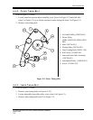
5.4.6. ULTRAMITTENT ASSEMBLY
Disassembly of Ultramittent or attempted repair of components will
void warranty.
Refer to item 5 on page 2-3.
1. Relieve tension on outer timing belt (see Section 5.4.2).
2. Remove two flat Allen head screws securing Ultramittent shoe.
3. Remove Ultramittent shoe closure assembly.
4. Remove four Allen head screws and washers securing Ultramittent assembly to
mainframe.
5. Carefully slide Ultramittent assembly out from non-operating side of projector.
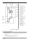
5.4.7. REMOVAL OF LED SOUND- HEAD AND SOLAR CELL ASSEMBLY
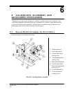
Refer to item 10 on page 2-2 and on page 2-3. See also Figure 6-1 on page 6-1.
1. Disconnect two LED leads at terminal blocks TB3-1 and TB3-2.
2. Disconnect solar cell wiring at LED pre-amp.
3. Remove four Allen head screws in corners of sound-head mounting plate.
4. Remove sound-head assembly.
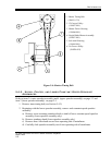
5.4.8. REMOVAL OF D IGITAL SOUND-HEAD A SSEMBLY
Refer to item 10 on page 2-2 and on page 2-3. See also Figure 6-2 on page 6-4.
1. Disconnect wiring at terminal blocks TB3-1, TB3-2, TB3-4, and TB3-5.
2. Disconnect solar cell wiring at LED pre-amp.
3. Disconnect video cable for CCD assembly.
4. Remove four Allen head screws in corners of sound-head mounting plate.
5. Remove sound-head assembly.
5.4.9. REMOVAL OF E LECTRIC CHANGEOVER ASSEMBLY
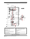
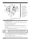
Refer to item 12 in Figure 5-3 on page 5-4.
1. Carefully pull four quick connect lugs from electric changeover assembly.
2. Loosen Allen screw on dowser hub, which clamps onto flex shaft.