


Maintenance
CHRISTIE DIGITAL SYSTEMS P35GPS Projector
March, 2004
5-7
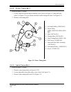
3. Remove flexible shaft from dowser blade.
4. Remove two Allen head screws securing electric changeover assembly to mainframe.
5. Remove changeover assembly.
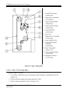
5.4.10. REMOVAL OF S HUTTER DRIVER ASSEMBLY
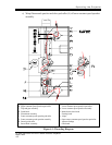
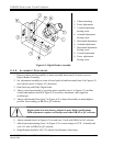
Refer to item 7 in Figure 5-3 on page 5-4.
1. Relieve tension on outer timing belt (Section 5.4.2).
2. Relieve tension on inner timing belt (Section 5.4.3).
3. Relieve tension on shutter timing belt (Section 5.4.4).
4. Remove four Allen head screws securing shutter driver assembly.
5. Remove shutter driver assembly.
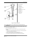
5.4.11. REMOVAL OF M OTOR ASSEMBLY
Refer to item 16 on page 2-3.
1. Disconnect motor's electrical leads at terminal block TB1-1 and TB1-2 (Figure 3-3 on
page 3-4).
2. Relieve tension on outer timing belt (Section 5.4.2).
3. Remove two cable ties holding motor cable in place by removing two Allen head cap
screws.
4. Remove four Allen head screws securing mounting plate with motor to motor bracket.
5. Remove motor assembly.
5.4.12. REMOVAL OF F AN
Refer to item 12 on page 2-2.
1. Remove four screws and washers securing fan to top plate of projector.
2. Pull fan up and remove A-C plug.
3. Remove fan.
5.4.13. REMOVAL OF F RAMING LAMP
1. Open framing lamp door, which is secured by two quarter-turn fasteners (item 13 on
page 2-2).
2. Remove lamp as with ordinary light bulb.