


P35GPS Dual Lens Turret Projector
CHRISTIE DIGITAL SYSTEMS P35GPS Projector 6-8
March, 2004
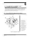
6.6.4. Timing Adjustments – Turret and Aperture Motor
The turret motor and the aperture motor are controlled from the PC board, which is mounted
on the non-operator side of the projector. Both motors are timed. One timer goes to the
FLAT position; another timer goes to the SCOPE position. The on-time for the FLAT position is
adjusted with a trimpot located at the lower side of the PC board.
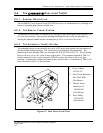
When user is facing front of projector, lensholder plate rotates
clockwise to
SCOPE position and counter-clockwise to FLAT position. If
lensholder plate turns in opposite direction, reverse quick-connects on
turret motor.
Turning the trimpot clockwise shortens the time. The timing is set approximately 0.5
seconds longer than the time needed for the turret motor to turn the lensholder plate from the
FLAT position to the SCOPE position and vice versa. The drive wheel will overrun for 0.5
second. The SCOPE on-time is adjusted in the same manner, using the trimpot located on the
upper side of the PC board.
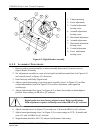
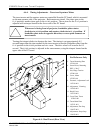
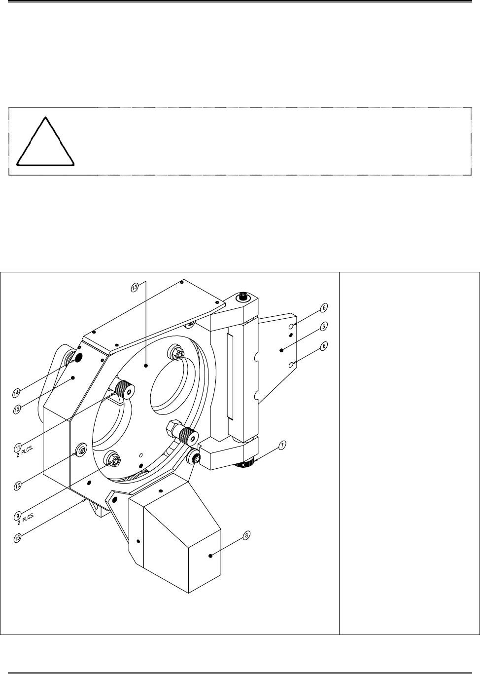
For Reference Only
5: Turret Mounting Plate
197014-001
6: Screw Holes, Mounting
SHC ¼-20x1”
7: Nut, Hinge Tension
197001-001
8: Cover, Motor
197022-001
9: Eccentric, Adjustment Lock
197036-001
10: Adjustment, V-bearing
197009-001
11: Knob, Focus
197034-001
12: Cover Plate, Turret
197043-001
13: Turret Main Plate
197031-001
14: Adjustment, Flat Stop
194955-001
15: Adjustment, Scope Stop
194956-001
Figure 6-4: Dual Turret (Rear View)