


Maintenance
CHRISTIE DIGITAL SYSTEMS P35GPS Projector
March, 2004
5-5
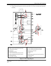
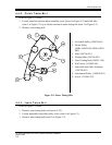
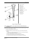
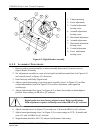
1: Shutter Timing Belt
(598931-533)
2: 12-Groove Pulley
(194827-001)
3: Shutter Driver Housing
(194866-001)
4: Single Blade Shutter Assembly
(194697-001)
5: Jack-shaft Housing
(194810-001)
6: 16-Groove Pulley
(194824-001)
Figure 5-4: Shutter Timing Belt
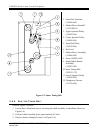
5.4.5. UPPER, CENTER, AND L OWER CONSTANT-SPEED SPROCKET
A SSEMBLIES
Refer to items 3 (center sprocket assembly) and 4 (upper sprocket assembly) on page 2-2 and
item 2 (lower sprocket assembly) on page 2-3.
1. Remove inner timing belt (see Section 5.4.3).
2. Beginning with the lower sprocket assembly, remove each constant speed sprocket
assembly:
a) Remove screw mounting turndown knob to shaft of lower constant-speed sprocket
assembly (lower sprocket assembly only).
b) Remove turndown knob (lower sprocket assembly only).
c) Remove three Allen head screws from operating side of mainframe.
d) Carefully slide sprocket assembly out of non-operating side of mainframe.