


8-9
Cisco ONS 15310-CL and Cisco ONS 15310-MA Ethernet Card Software Feature and Configuration Guide R8.5
78-18133-01
Chapter 8 Configuring IEEE 802.1Q Tunneling and Layer 2 Protocol Tunneling on the ML-Series Card
Understanding Layer 2 Protocol Tunneling
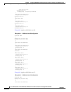
no ip address
no ip route-cache
mode dot1q-tunnel
bridge-group 10
bridge-group 10 spanning-disabled
!
interface POS0.1
encapsulation dot1Q 10
no ip route-cache
bridge-group 10
Understanding Layer 2 Protocol Tunneling
Customers at different sites connected across a service-provider network need to run various Layer 2
protocols to scale their topology to include all remote sites, as well as the local sites. Spanning Tree
Protocol (STP) must run properly, and every VLAN should build a proper spanning tree that includes the
local site and all remote sites across the service-provider infrastructure. Cisco Discovery Protocol (CDP)
must discover neighboring Cisco devices from local and remote sites. VLAN Trunking Protocol (VTP)
must provide consistent VLAN configuration throughout all sites in the customer network.
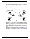
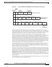
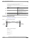
When protocol tunneling is enabled, edge switches on the inbound side of the service-provider
infrastructure encapsulate Layer 2 protocol packets with a special MAC address and send them across
the service-provider network. Core switches in the network do not process these packets, but forward
them as normal packets. CDP, STP, or VTP Layer 2 protocol data units (PDUs) cross the
service-provider infrastructure and are delivered to customer switches on the outbound side of the
service-provider network. Identical packets are received by all customer ports on the same VLANs with
the following results:
• Users on each of a customer’s sites are able to properly run STP and every VLAN can build a correct
spanning tree based on parameters from all sites and not just from the local site.
• CDP discovers and shows information about the other Cisco devices connected through the
service-provider network.
• VTP provides consistent VLAN configuration throughout the customer network, propagating
through the service provider to all switches.
Layer 2 protocol tunneling can be used independently or to enhance IEEE 802.1Q tunneling. If protocol
tunneling is not enabled on IEEE 802.1Q tunneling ports or on specific VLANs, remote switches at the
receiving end of the service-provider network do not receive the PDUs and cannot properly run STP,
CDP, and VTP. When protocol tunneling is enabled, Layer 2 protocols within each customer’s network
are totally separate from those running within the service-provider network. Customer switches on
different sites that send traffic through the service-provider network with IEEE 802.1Q tunneling
achieve complete knowledge of the customer’s VLAN. If IEEE 802.1Q tunneling is not used, you can
still enable Layer 2 protocol tunneling by connecting to the customer switch through access ports and
enabling tunneling on the service-provider access port.
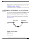
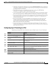
Configuring Layer 2 Protocol Tunneling
Layer 2 protocol tunneling (by protocol) is enabled on the tunnel ports or on specific tunnel VLANs that
are connected to the customer by the edge switches of the service-provider network. ML-Series card
tunnel ports are connected to customer IEEE 802.1Q trunk ports. The ML-Series card supports Layer 2