


17-8
Cisco ONS 15310-CL and Cisco ONS 15310-MA Ethernet Card Software Feature and Configuration Guide R8.5
78-18133-01
Chapter 17 CE-100T-8 Ethernet Operation
CE-100T-8 SONET Circuits and Features
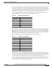
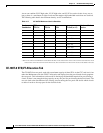
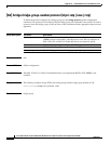
A user can combine CCAT high order, VCAT high order, and VCAT low order circuits in any way as
long as there is a maximum of eight circuits and the mapper chip bandwidth restrictions are observed.
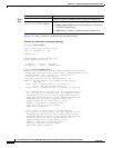
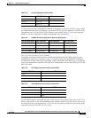
The following table details the maximum density service combinations.
* This LO-VCAT Circuit combination is achievable if the first circuit created on the card is an LO VCAT circuit. If the first circuit
created on the card is HO-VCAT or CCAT STS circuits, then a maximum of six LO-VCAT circuits can be added on the card.
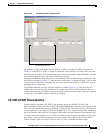
CE-100T-8 STS/VT Allocation Tab
The CE-100T-8 has two pools, each with a maximum capacity of three STSs. At the CTC card-level view
under the Maintenance tab, the STS/VT Allocation tab displays how the provisioned circuits populate
the two pools. This information can be useful in freeing up the bandwidth required for provisioning a
circuit, if there is not enough existing capacity on any one pool for provisioning the desired circuit. The
user can look at the distribution of the existing circuits among the two pools and decide which circuits
to delete in order to free up space for the desired circuit.
Table 17-7 CE-100T-8 Maximum Service Densities
Service
Combination
STS-3c or
STS-1-3v STS-1-2v STS-1 VT1.5-xV (x=1-7)
Number of Active
Service
12000 2
21110 3
31030 4
41007(x=1-12)*8*
50220 4
60116(x=1-14)8
70107(x=1-12)*8*
80060 6
90035(x=1-16)8
10 0 0 0 8 (x=1-21) 8