


14-8
Cisco ONS 15310-CL and Cisco ONS 15310-MA Ethernet Card Software Feature and Configuration Guide R8.5
78-18133-01
Chapter 14 Configuring Resilient Packet Ring on the ML-Series Card
Configuring RPR
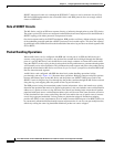
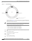
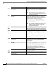
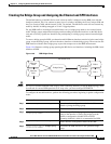
Figure 14-5 Three-Node RPR Example
The three-node RPR in Figure 14-5 is used for all of the examples in the consecutive RPR procedures.
Combining the examples will give you an end-to-end example of creating an RPR. It is assumed that the
SONET node and its network is already active.
Caution The specific steps in the following procedure are for the topology shown in the example. Your own
specific steps will vary according to your network. Do not attempt this procedure without obtaining a
detailed plan or method of procedure from an experienced network architect.
To configure the circuits, you need to create three circuits in CTC:
• Create a circuit from Node 1, POS Port 0 to Node 2, POS Port 1.
• Create a circuit from Node 2, POS Port 0 to Node 3, POS Port 1.
• Create a circuit from Node 3, POS Port 0 to Node 1, POS Port 1.
Step 1 In CTC, log into Node 1 and navigate to the CTC card view for the ML-Series card that will be in the
RPR.
Step 2 Click the Circuits > Create tabs.
The first page of the Circuit Creation wizard appears.
Step 3 In the Circuit Type list, select STS.
Step 4 Click Next.
The Circuit Attributes page appears.
Step 5 Type a circuit name in the Name field.
SPR 1
POS 1 POS 0
POS 0
POS 0
POS 1
POS 1
= STS circuit created on CTC
SPR Station-ID 2
SPR Station-ID 1
SPR Station-ID 3
124100