


14-23
Cisco ONS 15310-CL and Cisco ONS 15310-MA Ethernet Card Software Feature and Configuration Guide R8.5
78-18133-01
Chapter 14 Configuring Resilient Packet Ring on the ML-Series Card
Delete an ML-Series Card from an RPR
• Test Ethernet connectivity between the access ports on the existing adjacent ML-Series cards with
a test set to ensure that the RPR wrapped successfully.
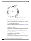
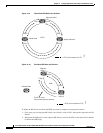
• Delete the two STS circuits that will be replaced by the new circuits. (In Figure 14-9, this is the
circuit between the Delete Node and one Adjacent Node, and the circuit between the Delete Node
and the other Adjacent Node.)
• Remove the Delete Node from the ring topology if desired.
• Physically remove the delete ML-Series card from the node if desired.
• Create an STS circuit from the available POS port of one of the remaining adjacent ML-Series cards
to the available POS port on the other remaining adjacent ML-Series card. (In Figure 14-10, this is
the circuit between Adjacent Node 2, POS Port 0 and Adjacent Node 1, POS Port 1.)
• Enable the POS ports on the existing adjacent ML-Series cards.(In Figure 14-10, this is the
Adjacent Node 2, POS Port 0 and the Adjacent Node 1, POS Port 1.)
• Test Ethernet connectivity between the access ports on the adjacent ML-Series card with a test set
to validate the two-node RPR.
• Monitor Ethernet traffic and existing routing protocols for at least an hour after the node deletion.
Caution The specific steps in the following procedure are for the topology in the example. Your own steps will
vary according to your network design. Do not attempt this procedure without obtaining a detailed plan
or method of procedure from an experienced network architect.
Deleting an ML-Series Card from an RPR
To delete an ML-Series card from an RPR, complete the following procedure:
Step 1 Start a Cisco IOS CLI session for the ML-Series card on the first adjacent node. This is Adjacent Node
1 in Figure 14-9.
Step 2 Complete the following Cisco IOS configuration on the ML-Series card in the first adjacent node,
beginning in global configuration mode:
Step 3 Start a Cisco IOS CLI session for the ML-Series card in Adjacent Node 2, as shown in Figure 14-9.
Step 4 Complete the following Cisco IOS configuration on the Adjacent Node 2 ML-Series card, beginning in
global configuration mode:
Step 5 Log into Adjacent Node 1 with CTC.
Step 6 Double-click the ML-Series card in Adjacent Node 1.
a.
Router(config)# interface pos
interface-number
Enters interface configuration mode for the POS port at the
end of the circuit directly connected to the Delete Node.
b.
Router(config-if)# shutdown
Closes the interface, which initiates the RPR wrap.
a.
Router(config)# interface pos
interface-number
Enters interface configuration mode for the POS port at the
end of the circuit directly connected to the Delete Node.
b.
Router(config-if)# shutdown
Closes the interface.