


6-4
Cisco ONS 15310-CL and Cisco ONS 15310-MA Ethernet Card Software Feature and Configuration Guide R8.5
78-18133-01
Chapter 6 Configuring STP and RSTP on the ML-Series Card
STP Features
BPDUs contain information about the sending switch and its ports, including switch and MAC
addresses, switch priority, port priority, and path cost. Spanning tree uses this information to elect the
root switch and root port for the switched network and the root port and designated port for each
switched segment.
Bridge ID, Switch Priority, and Extended System ID
The IEEE 802.1D standard requires that each switch has an unique bridge identifier (bridge ID), which
determines the selection of the root switch. Because each VLAN is considered as a different
logical bridge with PVST+, the same switch must have as many different bridge IDs as VLANs
configured on it. Each VLAN on the switch has a unique 8-byte bridge ID; the two most-significant bytes
are used for the switch priority, and the remaining six bytes are derived from the switch MAC address.
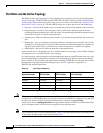
The ML-Series card supports the IEEE 802.1T spanning-tree extensions, and some of the bits previously
used for the switch priority are now used as the bridge ID. The result is that fewer MAC addresses are
reserved for the switch, and a larger range of VLAN IDs can be supported, all while maintaining the
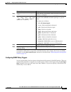
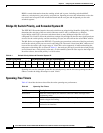
uniqueness of the bridge ID. As shown in Table 6-1, the two bytes previously used for the switch priority
are reallocated into a 4-bit priority value and a 12-bit extended system ID value equal to the bridge ID.
In earlier releases, the switch priority is a 16-bit value.
Spanning tree uses the extended system ID, the switch priority, and the allocated spanning-tree MAC
address to make the bridge ID unique for each VLAN.
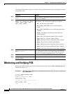
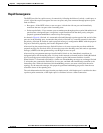
Spanning-Tree Timers
Table 6-2 describes the timers that affect the entire spanning-tree performance.
Table 6-1 Switch Priority Value and Extended System ID
Switch Priority Value Extended System ID (Set Equal to the Bridge ID)
Bit 16 Bit 15 Bit 14 Bit 13 Bit 12 Bit 11 Bit 10 Bit 9 Bit 8 Bit 7 Bit 6 Bit 5 Bit 4 Bit 3 Bit 2 Bit 1
32768 16384 8192 4096 2048 1024 512 256 128 64 32 16 8 4 2 1
Table 6-2 Spanning-Tree Timers
Variable Description
Hello timer When this timer expires, the interface sends out a Hello message to the
neighboring nodes.
Forward-delay timer Determines how long each of the listening and learning states last before the
interface begins forwarding.
Maximum-age timer Determines the amount of time the switch stores protocol information
received on an interface.