


14-20
Cisco ONS 15310-CL and Cisco ONS 15310-MA Ethernet Card Software Feature and Configuration Guide R8.5
78-18133-01
Chapter 14 Configuring Resilient Packet Ring on the ML-Series Card
Add an ML-Series Card into an RPR
Step 13 Use a test set to verify that Ethernet connectivity still exists between the Ethernet access ports on
Adjacent Node 1 and Adjacent Node 2.
Note The SPR interface and the Ethernet interfaces on the ML-Series card must be in a bridge group
in order for RPR traffic to bridge the RPR.
Step 14 If the new node is not already an active node in the SONET ring topology, add the node to the ring. Refer
to the “Add and Remove Nodes” chapter of the Cisco ONS 15454 Procedure Guide.
Step 15 If the ML-Series card in the new node is not already installed, install the card in the node. Refer to the
“Install the Cisco ONS 15310-CL” or “Install the Cisco ONS 15310-MA” chapters of the
Cisco ONS 15454 Procedure Guide.
Step 16 Upload the initial startup configuration file for the new ML-Series card. If you do not have a prepared
startup configuration file, manually create a startup configuration file.
Caution Ensure the new node is configured with RPR before its POS ports are manually enabled or enabled
through the configuration file.
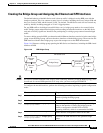
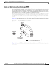
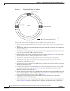
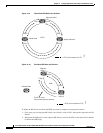
Step 17 Build an STS circuit with a circuit state of In Service (IS) from the available POS port on
Adjacent Node 1 to the New Node, as shown in Figure 14-8. On the New Node, use the POS port with
the interface-number that does not match the interface-number of the available POS port on
Adjacent Node 1. For example, POS Port 0 on Adjacent Node 1would connect to POS Port 1 on the
New Node.
For detailed steps for building the circuit, see the “Configuring CTC Circuits for RPR” section on
page 14-7.
Note A best practice is to configure SONET circuits in an east-to-west or west-to-east configuration,
from Port 0 (east) to Port 1 (west) or Port 1 (east) to Port 0 (west), around the SONET ring.
Step 18 Build an STS circuit with a circuit state of IS from the available POS port on Adjacent Node 2 to the
remaining POS port on the New Node, as shown in Figure 14-8.
Step 19 Start or resume a Cisco IOS CLI session for the ML-Series card in Adjacent Node 1, as shown in
Figure 14-7.
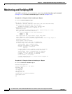
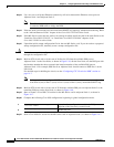
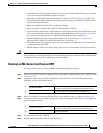
Step 20 Complete the following Cisco IOS configuration, beginning in global configuration mode:
Step 21 Start a Cisco IOS CLI session for the ML-Series card in Adjacent Node 2, as shown in Figure 14-7.
a.
Router(config)# interface pos
interface-number
Enters interface configuration mode for the POS port at one
endpoint of the first newly created circuit.
b.
Router(config-if)# no shutdown
Enables the port.