40
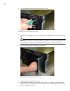
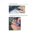
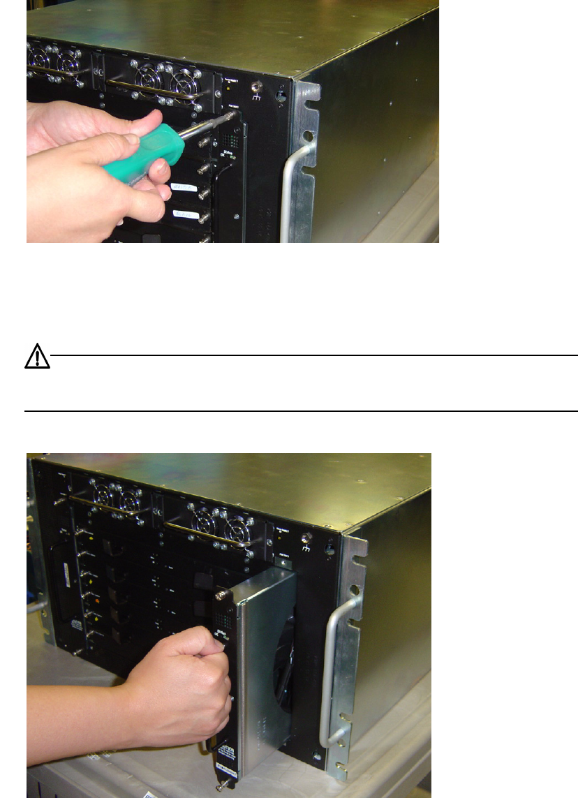
4. Use a #1 phillips screw driver to unscrew the captive screws.
Figure 3-5: Loosening Captive Screws
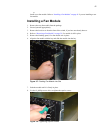
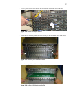
5. Carefully begin to pull the fan tray 1” out of the bay. Do not pull the fan tray completely from the
bay.
CAUTION: The fan tray does not have guards over the blades. You must wait until the fan blades
have stopped moving before completely removing the fan tray from the bay, or risk injury.
6. Wait 15 seconds to allow the fan blades to stop moving.
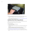
Figure 3-6: Partially Removing Fan Tray
7. Pull the fan tray completely out of the bay.
8. Install the blanking panel in place of the fan module. Only one fan module is required to run the
switch; however, the device should never be run without either a blanking panel or module in any
bay, as overheating may occur.


