


Site Requirements
Catalyst 8540 Chassis Installation Guide
2-6
• The height of the chassis is approximately 25 inches (62.5 cm). The rack must have
sufficient vertical clearance to allow insertion of the chassis.
When planning your rack installation, follow these guidelines:
• Allow at least 3 feet (1 m) of clearance in front of the rack for maintenance and removal
of the route processor, line modules, power supplies, and the fan assembly.
• Note that the ports for cooling air are located on the front, rear, and both sides of the
chassis, so multiple chassis can be rack-mounted with little or no vertical clearance.
However, avoid placing the chassis in an overly congested rack.
Warning To prevent overheating the chassis, do not operate it in an area that
exceeds the maximum recommended ambient temperature of 104°F (40°C). To
prevent airflow restriction, allow at least 3 inches (7.6 cm) of clearance around the
ventilation openings.
• Consider the equipment and cabling already installed in the rack. Ensure that cables
from other equipment do not obstruct the airflow through the chassis or impair access
to the power supplies or line modules. Route cables away from field-replaceable
components to avoid having to disconnect cables unnecessarily to perform equipment
maintenance or upgrades.
• Install heavier equipment in the lower half of the rack to maintain a low center of
gravity.
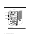
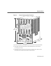
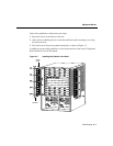
• Ensure that the shelf you place the chassis on can support the weight and dimensions of
the chassis. Use the chassis footprint, shown in Figure 2-1 if you are designing a
customized shelf.
Caution Never install the chassis in an enclosed rack that is not properly
ventilated or air-conditioned.