


Maintaining the Chassis 4-15
Replacing the Chassis Fan Assembly
Step 6 After ensuring that all wire connections are secure, reinstall the terminal block
cover.
To complete the installation, see the section “Powering Up the DC-Input Power Supply”
in this chapter.
Connecting the Redundant DC-Input Power Supply
To connect the redundant DC-input power supply to a separate input line, repeat the steps
in the previous section, “Connecting the DC-Input Power Supply,” but connect the
redundant unit to a different DC-input line from the initial power supply.
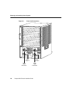
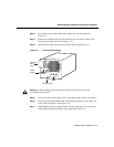
Powering Up the DC-Input Power Supply
To power up the DC power supply and confirm the installation, follow these steps:
Step 1 Remove the tape from the circuit breaker switch handle.
Step 2 Turn the power supply power switch on (|).
Step 3 Verify that the Input OK and Fan OK LEDs on the power supply front panel is
green. (See Figure 4-7.)
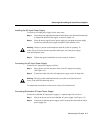
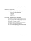
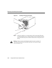
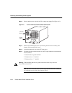
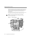
Replacing the Chassis Fan Assembly
This section describes how to replace the fan assembly, which is a single unit that draws in
cooling air and distributes it across the route processor, switch modules and line modules.
Caution Before performing any procedures in this chapter, review the sections
“Safety Recommendations,” “Ensuring Safety with Electricity,” and “Preventing
Electrostatic Discharge Damage” in the chapter “Installing the Chassis.”
Caution If you are replacing the fan assembly while the unit is operating, make
sure the replacement fan assembly is ready to be installed immediately.