


Maintaining the Chassis 4-17
Replacing the Chassis Fan Assembly
Tools Required
You need a 3/16-inch flat-blade screwdriver to remove the fan assembly.
Removing the Fan Assembly
To remove the existing chassis fan assembly, follow these steps:
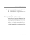
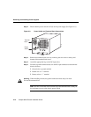
Step 1 Locate the fan assembly (see Figure 4-10) at the left of the module cage, above
the power supply.
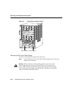
Step 2 Use a flat-blade screwdriver to loosen each of the two captive installation screws
by turning them counterclockwise.
Step 3 Loosen both screws on the chassis. These captive installation screws are fixed
to the fan assembly; do not attempt to completely remove them.
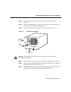
Step 4 Grasp the fan assembly with both hands and pull it toward you and away from
the backplane using steady pressure until it frees the backplane.
Step 5 Lift the fan assembly out of the chassis and place it in a safe place.
If the power has not been turned off, quickly proceed to the following section to reinstall a
fan assembly.
Caution Never operate the system if the fan assembly is not functioning
properly or if a fan assembly is not quickly reinstalled. An overtemperature
condition can result in severe equipment damage.
Installing a New Fan Assembly
To install the new fan assembly, follow these steps:
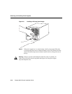
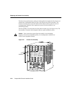
Step 1 Hold the fan assembly with the fans facing to the right.
Step 2 Place the fan assembly into the front chassis cavity so it rests on the chassis, and
then lift the fan assembly up slightly and align the top and bottom guides.
Step 3 Push the fan assembly into the chassis until the captive installation screws meet
the chassis.
Step 4 Tighten each of the two captive installation screws.