


Removing and Installing Power Supplies
Catalyst 8540 Chassis Installation Guide
4-6
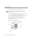
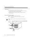
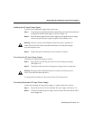
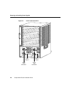
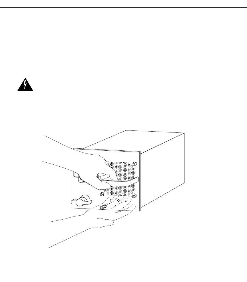
Step 6 While holding the power supply handle with one hand, place your other hand
underneath to support the bottom of the supply, as shown in Figure 4-4.
Step 7 Pull the power supply out of the bay and put it aside.
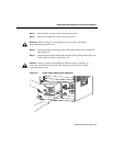
Step 8 If the power supply bay is to remain empty, install a filler plate over the opening
and secure it with the mounting screws.
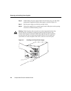
Warning Blank faceplates and cover panels serve three important functions: they
prevent exposure to hazardous voltages and currents inside the chassis; they
contain electromagnetic interference (EMI) that might disrupt other equipment;
and they direct the flow of cooling air through the chassis. Do not operate the
system unless all cards, faceplates, front covers, and rear covers are in place.
Figure 4-4 Handling an AC-Input Power Supply
16748