


Installing the Chassis 3-15
Connecting the System to the Grounding Pad
Connecting the System to the Grounding Pad
You must complete this procedure before connecting the system power or turning on the
switch.
To attach the grounding lug and cable to the grounding pad, perform these steps:
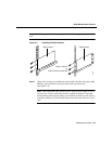
Step 1 Use a wire-stripping tool to remove approximately 0.75 inch (19 mm) of the
covering from the end of the grounding wire.
Step 2 Insert the stripped end of the grounding wire into the open end of the grounding
lug.
Step 3 Use a crimping tool to secure the grounding wire in place in the grounding lug.
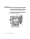
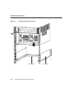
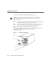
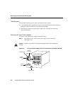
Step 4 Locate the grounding pad on the switch (See Figure 3-6.).
Step 5 Remove the label that covers the grounding pad.
Step 6 Place the grounding lug against the grounding pad.
Step 7 Insert two screws through the holes in the grounding lug and the grounding pad.
Ensure that the grounding lug will not interfere with other switch hardware or
rack equipment.
Step 8 Install the locking washers and nuts; tighten them to secure the grounding lug to
the grounding pad.
Step 9 Prepare the other end of the grounding wire and connect it to an appropriate
grounding point in your site to ensure adequate earth ground for the switch.
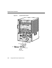
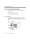
Installing the Power Supplies
As your communication requirements change, you might want to upgrade your system and
add or replace a power supply.
You need the following tools to remove and install a power supply:
• A 1/4-inch flat-blade screwdriver to remove and install filler plates and to loosen or
tighten the captive installation screw on the power supply.
• Filler plates to install over empty power supply bays to protect the connectors
from contamination.