


Removing and Installing Power Supplies
Catalyst 8540 Chassis Installation Guide
4-14
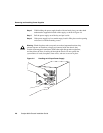
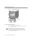
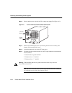
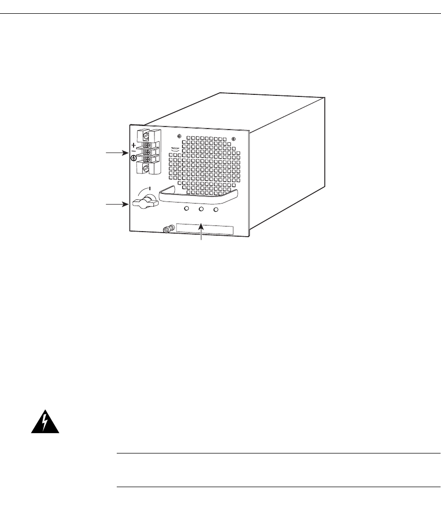
Step 2 Ensure that the power switch is off (0) on the power supply. (See Figure 4-9.)
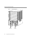
Figure 4-9 Power Switch and Terminal Block Connections
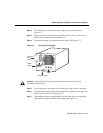
Step 3
Remove the terminal block cover by removing the two screws at the top and
bottom of the terminal block cover.
Step 4 Attach the appropriate lugs to the DC-input wires.
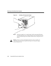
Step 5 From the top of the terminal block, wire the DC-input conductors to the terminal
block as follows:
• Ground wire to ground terminal
• Return wire to “+” terminal
• Battery wire to “−” terminal
Warning When installing the unit, the ground connection must always be made
first and disconnected last.
Note Be sure to route the wires from the top of the terminal block so that you
do not obstruct access to the chassis power switch.
o
15708
Power
switch
Terminal
block
LEDs
INPUT
OK
FAN
OK
OUTPUT
FAIL