


1-21
Cisco IP/TV 3400 Series Servers User Guide
OL-4467-01
Chapter 1 Introducing IP/TV Servers
Cisco IP/TV Broadcast Servers
Note The video capture cards do not have any LEDs.
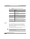
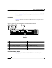
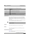
Input/Output Ports and Connectors
The Cisco IP/TV 3427 Broadcast Servers have the following I/O connectors:
• One dual-channel Ultra320 SCSI controller low-voltage differential (LVD)
SCSI port
• One serial port
• Two Ethernet ports
• Audio and video connectors
Warning
To avoid electric shock, do not connect safety extra-low voltage (SELV) circuits
to telephone-network voltage (TNV) circuits. LAN ports contain SELV circuits,
and WAN ports contain TNV circuits. Some LAN and WAN ports both use RJ-45
connectors. Use caution when connecting cables.
Statement 1021
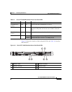
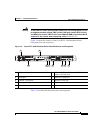
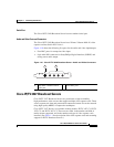
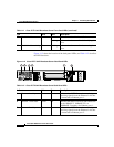
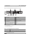
Figure 1-13 shows the Cisco IP/TV 3427 Broadcast Server back panel, and
Table 1-13 describes the back panel ports and connectors.
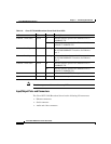
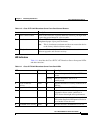
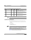
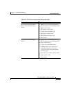
4 Ethernet 2 link status Green On Indicates there is an active link connection on
the 10BASE-T, 100BASE-TX, or
1000BASE-T interface for Ethernet port 2.
5 AC power Green On Provides status information about the power
supply. During typical operation, both the AC
and the DC power LEDs are on.
6 DC power Green On Provides status information about the power
supply. During typical operation, both the AC
and the DC power LEDs are on.
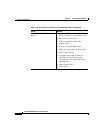
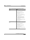
Table 1-12 Cisco IP/TV 3427 Broadcast Server Back Panel LEDs (continued)
Indicator Color State Description