


3-35
Cisco IP/TV 3400 Series Servers User Guide
OL-4467-01
Chapter 3 Installing the IP/TV Server
Checking the LEDs
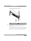
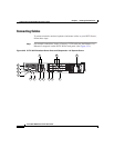
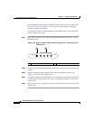
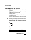
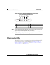
Figure 3-26 Optibase MovieMaker 200S Networker Video Capture
Card—Connecting to the Video Source
Step 2
Connect the other end of the video BNC connector cable or the S-video mini-DIN
cable to the appropriate ports on the video source device.
Step 3 Plug the audio connector cable from the video source device to the A IN port
(labeled 5 in Figure 3-26) on the video capture card.
Checking the LEDs
When the IP/TV Server is up and running, observe the front and back panel LEDs
to verify that your system is operating properly. (See Figure 1-3, Figure 1-7,
Figure 1-8, Figure 1-11, and Figure 1-12, and Table 1-2, Table 1-3, Table 1-7,
Table 1-8, Table 1-11, and Table 1-12.)
1 S-video port 2 Video in port
3 Video out port 4 Audio out port
5 Audio in port
96404
S-VIDEO
V IN
V OUT
A OUT
A IN
1 2 3 4 5