


1-3
Cisco ME 4924-10GE Ethernet Switch Hardware Installation Guide
OL-10071-01
Chapter 1 Product Overview
Front Panel Description
Optical Support
The switch supports Gigabit Ethernet SFP modules as described at these URLs:
• http://www.cisco.com/en/US/products/hw/modules/ps5455/products_device_support_table09186a00
80446625.html
• http://www.cisco.com/en/US/products/hw/modules/ps5455/products_device_support_table09186a00
80385874.html
The switch supports X2 modules as described at this URL:
• http://www.cisco.com/en/US/products/hw/modules/ps5455/products_device_support_table09186a00
803857e7.html
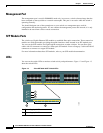
Front Panel Description
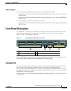
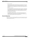
The 1000BASE-X Ethernet ports are numbered 1 through 24. These ports are grouped into pairs. The
first member of the pair (port 1) is above the second member (port 2) on the far left, as shown in
Figure 1-1. Port 3 is above port 4, and so on.
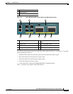
Figure 1-1 Cisco ME 4924-10GE Switch Front Panel
The standard SFP ports are numbered 1 to 24 (left to right). The uplink SPF ports are numbered 25 to 28
(left to right). The X2 module ports are numbered 29 and 30 (left to right).
Console Port
You can connect the switch to a PC by means of the console port and the supplied RJ-45-to-DB-9 female
cable. If you want to connect the switch console port to a terminal, you need to provide an
RJ-45-to-DB-25 female DTE adapter. You can order a kit (part number ACS-DSBUASYN=) containing
that adapter from Cisco. For console port and adapter pinout information, see the “Connector and Cable
Specifications” section on page B-1.
This port can be used to create an initial configuration as described in Appendix C, “Initial Configuration
for the Switch.”
1 24 Standard SFP ports 3 4 enhanced services SFP ports
2 Console and management ports 4 2 X2 module ports
13
14
15
16
17
18
19
20
21
22
23
24
1 2 3 4
Cisco ME 4924-10GE