


CHAPTER
3-1
Cisco ME 4924-10GE Ethernet Switch Hardware Installation Guide
OL-10071-01
3
Connecting the Power Supply
This chapter describes how to connect the AC and DC power supply units and to remove them.
See these sections:
• Grounding Requirements, page 3-1
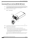
• Connecting AC Power to the Cisco ME 4924-10GE Switch, page 3-2
• Connecting DC Power to the Cisco ME 4924-10GE Switch, page 3-3
Warning
Only trained and qualified personnel should be allowed to install, replace, or service this equipment.
Statement 1030
Caution If you use only one power supply in your switch, always cover the other power bay with the bay cover.
Grounding Requirements
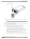
Grounding is recommended on all AC or DC installations, using only approved copper connectors.
Attach the provided two hole ground lug to the chassis using M4x 8mm bolts and then to the central
office (CO) or other interior ground system with number 6 AWG wire. The grounding connectors are on
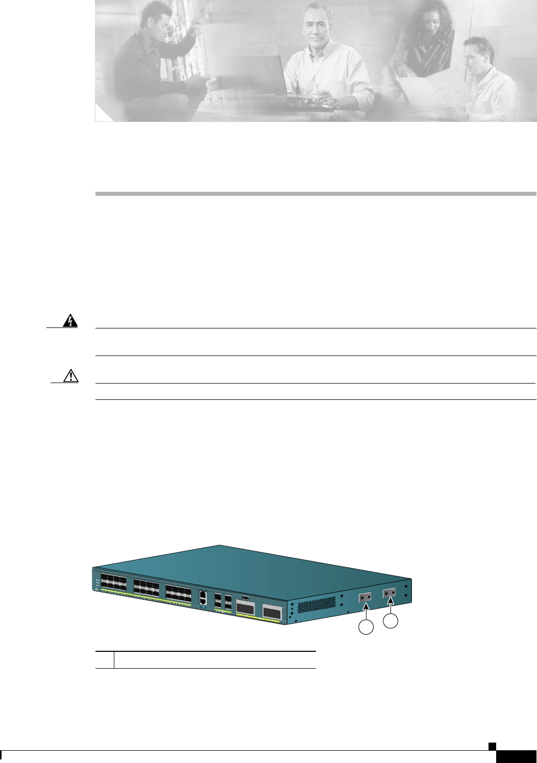
the right side of the chassis, and either one may be used.
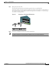
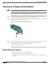
Figure 3-1 Grounding Pad Locations
1 Grounding pads
154919
1
3
1
4
1
5
1
6
1
7
1
8
1
9
2
0
2
1
2
2
2
3
2
4
1
1
C
is
c
o
M
E
4
9
2
4
-1
0
G
E