


1-5
Cisco ME 4924-10GE Ethernet Switch Hardware Installation Guide
OL-10071-01
Chapter 1 Product Overview
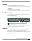
Front Panel Description
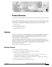
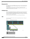
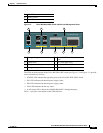
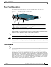
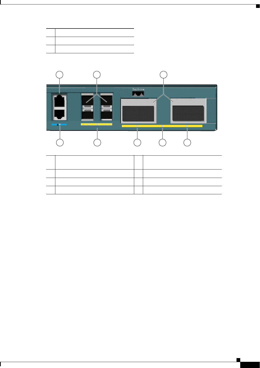
Figure 1-3 Cisco ME 4924-10GE Switch Uplinks and Management Ports
The LEDs on the front panel of the Cisco ME 4924-10GE switch (see Figure 1-2 and Figure 1-3) provide
status information as follows:
• STATUS LED indicates the operating state of the Cisco ME 4924-10GE switch.
• PS1 LED indicates the internal power supply status.
• PS2 LED indicates the internal power supply status.
• FAN LED indicates the fan tray status.
• A link status LED is below the 10/100/1000 BASE-T management port.
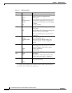
Table 1-1 provides a description of the LED functions.
3 FAN LED
4 STATUS LED
5 Port LED
1 Management port 5 Enabled LED for enhanced services
ports
2 Uplink SFPs 6 X2-1 Port status LED
3 X2 ports 7 Enabled LED for X2 Ports
4 Management port LED 8 X2-2 Port status LED
154872
Cisco ME 4924-10GE
25 26 ENABLED 27 28
29
30ENABLED
CON MGMT
54 6 7 8
1 2 3