


1-7
Cisco ME 4924-10GE Ethernet Switch Hardware Installation Guide
OL-10071-01
Chapter 1 Product Overview
Rear Panel Description
Rear Panel Description
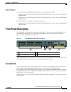
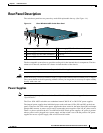
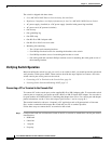
The switch rear panel has two power bays anda field replaceable fan tray. (See Figure 1-4.)
Figure 1-4 Cisco ME 4924-10GE Switch Rear Panel
The hot-swappable system fan tray provides cooling air for the internal chassis components. The fans
exhaust air to the rear, and fresh air is drawn in from the sides of the chassis.
Note For environmental specifications, see Chapter 2, “Site Planning.”
Caution When the fan tray is removed, internal circuitry is exposed that should not be touched by tools or fingers.
The system should not be left operating without a fan tray for longer than is necessary to replace a faulty
fan tray with a new one.
Power Supplies
Note For complete power specifications for the Cisco ME 4924-10GE switch, see Appendix A,
“Specifications.”
The Cisco 4924-10GE switch has two redundant internal 300 W AC or 300 W DC power supplies.
The internal power supplies have individual power cords and status LEDs (PS1 and PS2 on the front
panel). There are also LEDs on the power supplies that show status for the input (Input OK) and output
(Output OK) currents. A power cord is used to connect the power supplies to the site AC power source.
There is a power switch on the AC Cisco ME 4924-10GE switch power supplies; AC power is present
when a power cord is plugged into a power supply and the switch is set to the On position. DC power
supplies do not use a power supply cord or have an on/off switch
1 Power supply PS1 on/off switch 5 Power supply PS2 AC cable connection
2 Power supply PS2 on/off switch 6 Power supply PS2
3 Power supply PS1 AC cable connection 7 Fan tray
4 Power supply PS1
154871
1
2
3
5
7
4
6