


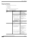
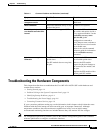
3-2
Cisco ME 4924-10GE Ethernet Switch Hardware Installation Guide
OL-10071-01
Chapter 3 Connecting the Power Supply
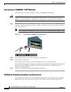
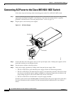
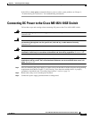
Connecting AC Power to the Cisco ME 4924-10GE Switch
Connecting AC Power to the Cisco ME 4924-10GE Switch
Follow these steps and warnings when connecting power to the Cisco ME 4924-10GE switch:
Step 1 Prior to connecting the power supply to a power source, ensure that all of the site power and grounding
requirements described in Chapter 2, “Site Planning,” have been met and the chassis is properly
grounded as described in the “Grounding Requirements” section on page 2-4.
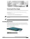
Step 2 Plug the power cords into the power supplies.
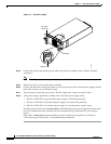
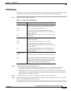
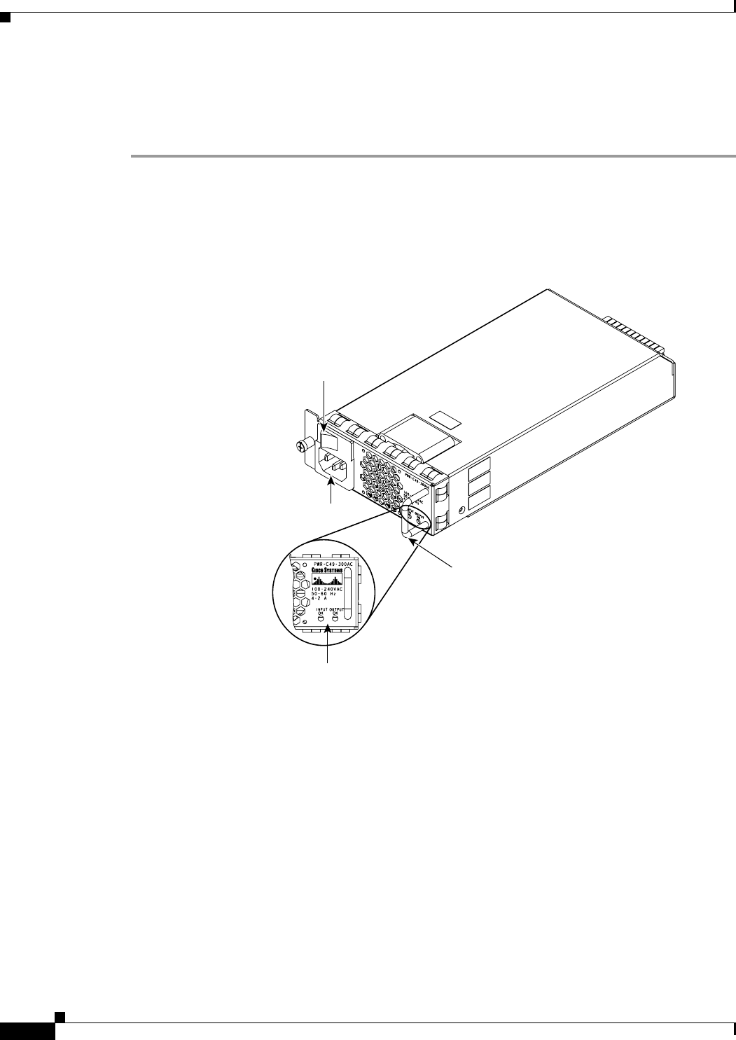
Figure 3-2 AC Power Supply
Step 3
Connect the other end of the power cords to an AC-power input source. If both power supplies will be
used, make sure they are on different circuits.
Step 4 Turn the power switches to the ON position.
Step 5 Verify power supply operation by looking at the front panel power supply LEDs:
• The PS1 or PS2 LED is green when the power supply and fans are functioning normally.
• The PS1 or PS2 LED is red when the power supply is not functioning normally. The on/off switch
may be set to off while the power supply is plugged in, or the power supply may be defective and
not providing DC power to the switch. There may also be a fan failure.
• The PS1 or PS2 LED is off when there is no power supply installed.
From the system console, enter the show power command to display the power supply and system status.
For more information on this command, see the command reference publication for your software
release.
Status LEDs
AC power plug
Handle
On/off switch
120696