


B-2
Cisco ME 4924-10GE Ethernet Switch Hardware Installation Guide
OL-10071-01
Appendix B Connector and Cable Specifications
Connector Specifications
Warning
Invisible laser radiation may be emitted from disconnected fibers or connectors. Do not stare into
beams or view directly with optical instruments.
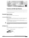
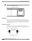
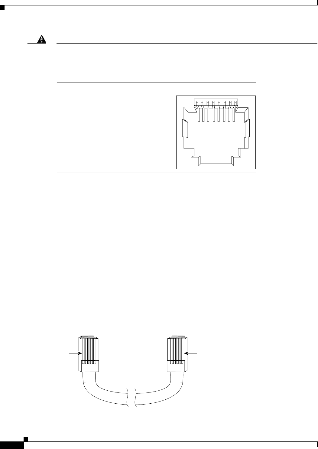
Figure B-2 Copper SFP Module RJ-45 Connector
Console Port
The console port uses an 8-pin RJ-45 connector, which is described in Table B-1 on page B-3 and
Table B-2 on page B-3. The supplied RJ-45-to-DB-9 adapter cable is used to connect the console port of
the switch to a console PC. You need to provide a RJ-45-to-DB-25 female DTE adapter if you want to
connect the switch console port to a terminal. You can order a kit (part number ACS-DSBUASYN=)
containing that adapter from Cisco. For console port and adapter pinout information, see Table B-1 on
page B-3 and Table B-2 on page B-3.
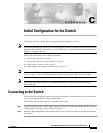
Identifying a Crossover Cable
To identify a rollover cable, compare the two modular ends of the cable. Hold the cable ends
side-by-side, with the tab at the back. The wire connected to the pin on the outside of the left plug should
be the same color as the wire connected to the pin on the outside of the right plug. (See Figure B-3.)
Figure B-3 Identifying a Crossover Cable
60915
231 45678Pin Label
1
2
3
4
5
6
7
8
TP0+
TP0-
TP1+
TP2+
TP2-
TP1-
TP3+
TP3-
Pin 1
H10632
Pin 8
Pin 1 on one connector and
pin 8 on the other connector
should be the same color.