


CHAPTER
4-1
Cisco ME 4924-10GE Ethernet Switch Hardware Installation Guide
OL-10071-01
4
Troubleshooting
The LEDs on the front panel provide troubleshooting information about the switch. They show failures
in the power-on self-test (POST), port-connectivity problems, and overall switch performance. For a full
description of the switch LEDs, see the “LEDs” section on page 1-4.
You can also get statistics from the command-line interface (CLI) or from a Simple Network
Management Protocol (SNMP) workstation. Refer to the software configuration guide, the switch
command reference guide on Cisco.com, or the documentation that came with your SNMP application
for details.
This chapter describes these topics for troubleshooting problems:
• Understanding POST Results, page 4-1
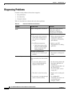
• Diagnosing Problems, page 4-2
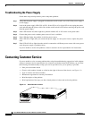
• Troubleshooting the Hardware Components, page 4-3
• Contacting Customer Service, page 4-6
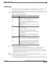
Understanding POST Results
When the switch powers on the PS1, PS2, and FAN LEDs should all be green. If one of the power
supplies is off or has insufficient power to work, its LED will be red. If the fan tray has a problem the
FAN LED will be red. The switch immediately begins POST (Power on Self-Test), a series of tests that
run automatically to ensure that the switch functions properly. When the switch begins POST, the
STATUS LED flashes amber, and it should flash for about a minute.
When the POST is complete and the switch has passed, the STATUS LED turns green. If problems were
detected on individual ports, the link LED for that port will flash amber. The switch may still pass traffic
depending on the type of error.
If the switch fails POST, the STATUS LED stays a steady amber and stops blinking. Port link LEDs are
off.
Note For information on operating status for the LEDs, go to the “LEDs” section on page 1-4.
Note POST failures are may or may not be fatal. Check console output for the nature of the failure and call
Cisco Systems if your switch does not pass POST.